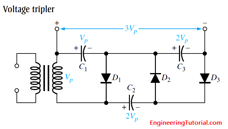
The addition of another diode-capacitor section to the half-wave voltage doubler creates a voltage tripler, as shown in Below Figure.
The operation is as follows: On the positive half-cycle of the secondary voltage, C1 charges to Vp through D1. During the negative halfcycle, C2 charges to 2Vp through D2, as described for the doubler. During the next positive half-cycle, C3 charges to 2Vp through D3. The tripler output is taken across C1 and C3, as shown in the figure.

