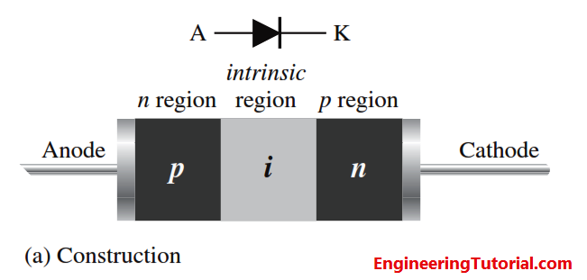
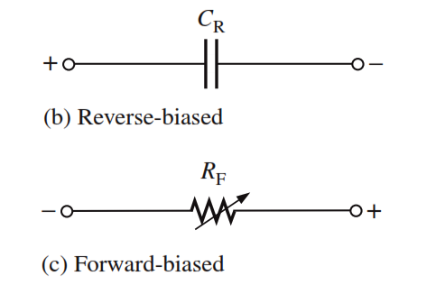
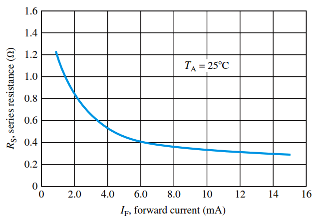
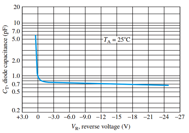
The pin diode consists of heavily doped p and n regions separated by an intrinsic (i) region, as shown in Figure (a). When reverse-biased, the pin diode acts like a nearly constant capacitance. When forward-biased, it acts like a current-controlled variable resistance. This is shown in Figure (b) and (c). The low forward resistance of the intrinsic region decreases with increasing current.
The PIN diode operates in exactly the same way as a normal diode. The only real difference is that the depletion region, that normally exists between the P and N regions in an unbiased or reverse biased diode is larger.
In any PN junction, the P region contains holes as it has been doped to ensure that it has a predominance of holes. Similarly the N region has been doped to contain excess electrons. The region between the P and N regions contains no charge carriers as any holes or electrons combine As the depletion region has no charge carriers it acts as an insulator.
Within a PIN diode the depletion region exists, but if the diode is forward biased, the carriers enter the depletion region (including the intrinsic region) and as the two carrier types meet, current starts to flow.
When the diode is forward biased, the carrier concentration, i.e. holes and electrons is very much higher than the intrinsic level carrier concentration. Due to this high level injection level, the electric field extends deeply (almost the entire length) into the region. This electric field helps in speeding up of the transport of charge carriers from p to n region, which results in faster operation of the diode, making it a suitable device for high frequency operations.
PIN Diode VI Characteristics
The forward series resistance characteristic and the reverse capacitance characteristic are shown graphically in Below Figure for a typical pin diode. The pin diode is used as a dc-controlled microwave switch operated by rapid changes in bias or as a modulating device that takes advantage of the variable forward-resistance characteristic. Since no rectification occurs at the pn junction, a high-frequency signal can be modulated (varied) by a lower-frequency bias variation. A pin diode can also be used in attenuator applications because its resistance can be controlled by the amount of current. Certain types of pin diodes are used as photodetectors in fiber-optic systems.
Advantages of PIN diode
The PIN diode is used in a number of areas as a result of its structure proving some properties which are of particular use.
- High voltage rectifier: The PIN diode can be used as a high voltage rectifier. The intrinsic region provides a greater separation between the PN and N regions, allowing higher reverse voltages to be tolerated.
- RF switch: The PIN diode makes an ideal RF switch. The intrinsic layer between the P and N regions increases the distance between them. This also decreases the capacitance between them, thereby increasing he level of isolation when the diode is reverse biased.
- Photodetector: As the conversion of light into current takes place within the depletion region of a photdiode, increasing the depletion region by adding the intrinsic layer improves the performance by increasing he volume in which light conversion occurs.
These are three of the main applications for PIN diodes, although they can also be used in some other areas as well.
The PIN diode is an ideal component to provide electronics switching in many areas of electronics. It is particularly useful for RF design applications and for providing the switching, or attenuating element in RF switches and RF attenuators. The PIN diode is able to provide much higher levels of reliability than RF relays that are often the only other alternative.
Disadvantages of PIN diode
- Has a reverse recovery time which contributes to power loss
Related Articles :
Engineering Tutorial Keywords:
- disadvantages of pin diode
