It can be quite useful to determine how a voltage appearing across two series resistors “divides” between them.
Consider the circuit shown below:
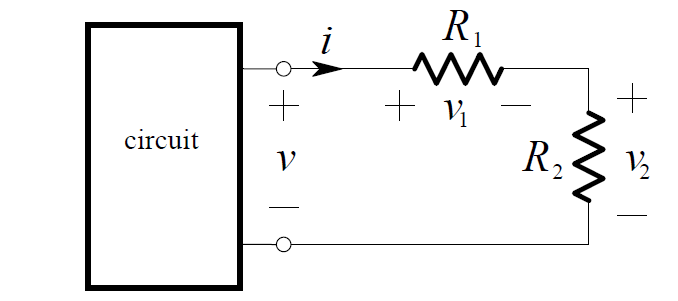
By Ohm’s Law, the current in the resistors is:
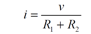
By application of Ohm’s Law again, the voltage across R1 is:
v1 = R1 . i
and therefore:

Similarly, the voltage across R2 is:

These equations describe how the voltage is divided between the resistors. Because of this, a pair of resistors in series is often called a voltage divider.
Example:
We want to find the voltage v in the circuit below:
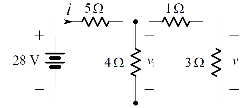
Combining the series connection of the 1 ohm and 3 ohm resistors, we obtain the
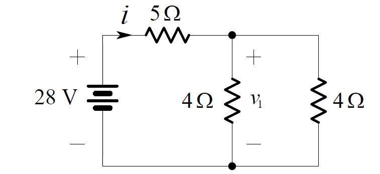
Now the pair of 4 ohms resistors in parallel can be combined as shown below:
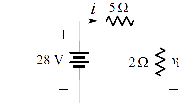
By voltage division:

Returning to the original circuit and applying voltage division again yields:

