What are the main functions of control gear?
- To provide a means of starting and stopping the motor and, at the same time, of limiting the starting current if required.
- To give adequate protection to the motor under all conditions.
- To allow speed changing when required.
- To provide means of braking the motor when required.
- To reverse the direction of rotation when required.
Protection of the motor must be automatic, but the other operations may be arranged to be under the control of an operator, or may be partly or fully-automatic.
What devices are required to give adequate protection to the motor?
- Under-voltage release to prevent automatic restarting after a stoppage due to a drop in voltage or failure of the supply, where unexpected restarting of the motor might cause injury to an operator.
- Overload relays for protection against excessive current in the motor windings – e.g. in the event of overload or failure of the motor.
- Earth fault.
- Single phase protection.
What provision must be made for short-circuit conditions in motor circuits?
Since overload relays are not designed to operate and clear the circuit in the event of a short-circuit. Circuit-breaker or fuse protection of sufficient breaking capacity to deal with any possible short-circuit that may occur must be provided.
What are the usual forms of overload relay in motor-control gear?
In small contactor starters, generally thermal relays, either of the ‘solder pot’ or bimetal type. With large contactors or oil switches, magnetic relays of the solenoid type with dashpots. Either type of overload relay may be used within intermediate sizes.
How do thermal relays work?
The bimetallic thermal relay consists of a small bimetallic strip that is heated by an element connected in series with the supply. When the current rises above a preset value, the movement of the strip releases a catch which opens the trip contacts.
In recent years more modern electronic relays are used which simulate the thermal overload. Many of these relays also incorporate a memory, i.e. simulates the temperature rise / cooling curve of the winding.
How does the magnetic overload relay operate?
A solenoid connected in series with the supply contains a plunger whose movement is damped by a dashpot. When the safe current is exceeded, the solenoid pulls the plunger up – disconnecting the supply. The damping provided by the dashpot prevents unwarranted tripping on short-time overloads.
How many overload relays are required in the control gear?
On three-phase supplies where the neutral point of the system is connected to earth, as is usually the case, three overload relays (one in each line) are necessary for complete protection.
For 2-phase 3-wire and 4-wire supplies, two overload relays are required, one in each phase line, none being connected in any neutral or earth conductor.
With single-phase motors one overload relay in any conductor except an earthed conductor or neutral.
What happens when one of the three lines supplying a three-phase induction motor becomes open-circuited?
The motor, if already running, will continue to run as a single-phase motor on the remaining single-phase supply. The condition is called single-phasing. If the motor is loaded to more than about 30 per cent of full load, the currents in the motor windings tend to become excessive and overheating occurs.
With one line broken, the motor will not start up and, due to the heavy standstill current, burn-out is likely unless the motor is quickly disconnected.
What currents flow in a single-phasing delta-connected motor?
Assuming that supply line L1 is open circuited as shown, typical line and phase currents, given as percentages of normal full-load three-phase current, at various loads will be:-
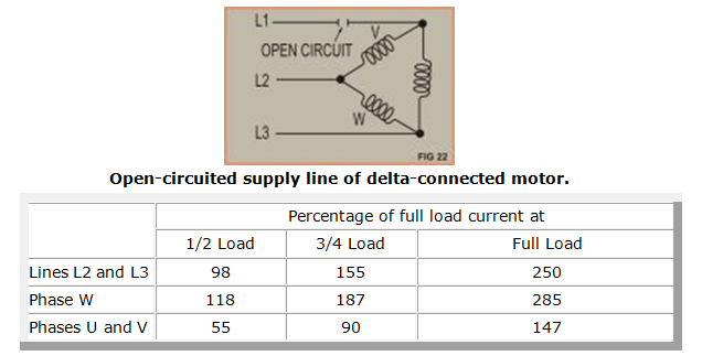
Thus, phase W connected across the two operative lines carries nearly three times normal current under single-phasing conditions at full load, while phases U and V, which are in series, carry more than full-load current.
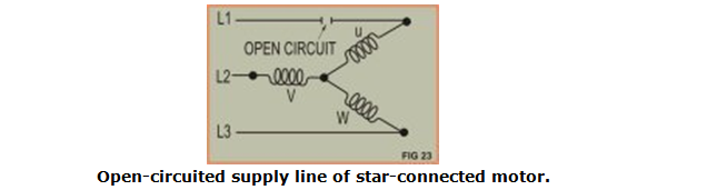
What currents flow in a single-phasing star-connected motor?
Assuming that line L1 is open-circuited as shown, the current flowing at full load in lines L2 and L3 and through the two phases in series will be of the order of 250 percent of normal full-load current, 155 per cent on 3/4-load and 98 per cent on 1/2-load.
Will normal overload relays trip on single-phasing?
If correctly set, the normal overloads will trip when the motor is fully loaded due to the rise in current passing through the closed supply lines. With a delta-connected motor partially loaded, the rise in line current may not be sufficient to operate the overload trip and one phase may became excessively overheated.
What special protection can be provided against single-phasing?
One method is to incorporate a combined overload and single-phase relay in the control gear. A typical relay of this type includes three overload relays with trip contacts so arranged that it will trip if the displacement of one overload element differs from that of the others.
This type of relay will operate if single-phasing occurs at or near full load with the same time delay as on overload, but at light loads, the time delay for single-phase protection is longer. Another device is a phase-failure relay in the control gear. Its principle is based on the fact that the currents in the supply lines or the voltages between them at the motor terminals are unbalanced when the motor is single-phasing.
The phase-failure relay may be of the current or voltage-operated type which trips out the line switch when one of the supply lines becomes open circuited.
What are the alternatives to the use of overload releases?
Direct protection against overheating or burning-out of motor windings may be built into the motor. Built-in protectors may take the form of thermostats or thermistors embedded in the end windings of the stator while the motor is under construction. These devices are sensitive to the winding temperatures and are arranged in a suitable circuit so as to cause the motor to be switched off if the windings heat up excessively.
How are built in thermal overload protector arranged?
On smaller motors LV mush winding motors, these detectors are embedded in the overhang of the winding. On the medium voltage motors these are placed in between bottom and top coils in the slot portion of the core.
How do built-in thermal overload protectors work?
Thermistors are very small semiconductor devices whose resistance changes rapidly with temperature. Three thermistors are inserted in the end-windings of the stator, one in each phase, and are connected in series. The two thermistor terminals at the motor are connected to an electronic-amplifier-control unit in the starter, through which the tripping circuit of the starter is operated. The response of the thermistors to temperature change is extremely rapid, allowing this type of protection to be effective under all motor overload conditions.
Resistance temperature devices (RTD)
This is a resistance which increases linearly with temperature rise. The most commonly used in motors is embedded in an epoxy glass type wedge which can be inserted between the upper and lower coils. The resistance is measured with an electronic amplifier control unit which is converted to temperature.
This unit has adjustable settings to allow for alarm and trip with contacts which are then used in the motor starter circuit.
Thermocouples
A thermocouple is two dissimilar metals which are joined together and with a change in temperature, creates a voltaic action. This gives out a milli-volt signal which is then measured with an electronic amplifier control unit converting the measurement to temperature.
When is direct-on-line starting used for three-phase squirrel-cage motors?
It is usual for small LV machines; for larger motors it is often necessary to use other methods of starting in order to ovoid excessive starting currents. HV motors are usually DOL started. (since amps are low)
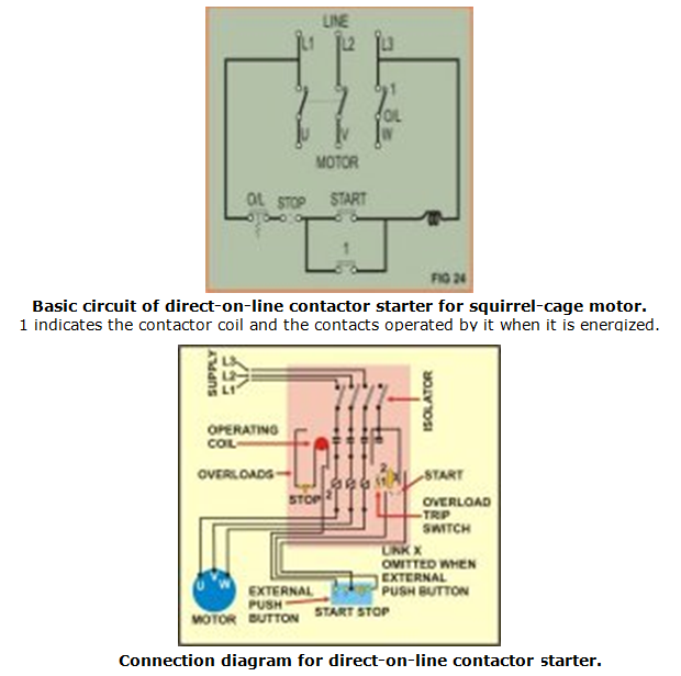
What are the connections for direct-on-line starters?
The scheme of connections is merely three line leads in and three motor leads out. Direct-on-line contactor starters are designed round the basic circuit shown. An isolating switch may be incorporated in the starter. If reversing is required, two contactors one for each rotation, are required and are interlocked so that only one can close at a time.
A hand-operated oil switch with under-voltage trip coil may be used with larger motors.
What methods are employed to reduce the starting current of squirrel-cage motors?
Where the starting conditions are light, the starting current can be lessened by some method of reducing the stator voltage when switching on. There are four ways of starting on reduced voltage:
- Primary-resistance starting – introducing resistance between the supply and the stator windings.
- Primary-reactor starting – introducing a reactor in series with the stator windings, usually connected in the star point.
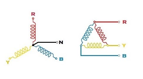
- Star-delta starting – connecting the stator windings in star for starting and in delta for running.
- Auto-transformer starting – supplying the stator windings through tappings on an auto-transformer.
When is primary-resistance starting employed?
Generally only for small motors on light-starting duty. The method is easily adjustable to suit the load and gives a smooth breakaway against low torque. If the resistance is adjustable, as in a faceplate starter, starting can be very smooth and this is useful for motors that must be started without any shock that might cause injury to the material being handled by the driven machine.
When is the primary reactor method of starting employed?
Mainly for high-tension motors on very light-starting load where a fairly heavy starting current can be permitted e.g. boiler-feed pumps in a large power station.
When is the star-delta starter used?
When the starting current has to be reduced and starting current and torque values one-third of those obtained with direct-on-line starting are suitable. It is necessary that the motor be designed to operate with the primary winding connected in delta, but with six terminals brought out to allow for connection in star during starting.
The plain star-delta method is used for small and medium-sized motors on light-starting loads, e.g. centrifugal pumps, fans having low inertia, line shafting and motor-generator sets. The Wauchope-type has the same uses but prevents the drop in speed when the stator is disconnected from the supply in changing from star to delta. Switching is done through resistances to maintain continuous line contact. This also obviates the momentary high current when switching from star to delta.
What are the connections for a star-delta starter?
Motors arranged for star-delta starting have six terminals – the two ends of each phase winding being brought out to terminals marked U1, V1, W1 and U2, V2, W2. These terminals are connected to similarly-marked terminals in the starter.
The basic circuit of a typical hand-operated air-break or oil-immersed starter is shown in the diagram, the incoming supply being controlled by a line contactor. With the change-over switch in the start position, the motor windings are connected in star (U1, V1 and W1 together) and in the running position in delta (U2 to W1, V2 to U1 and W2 to V1).
In starting the motor, the handle of the change-over switch is put into the start position, as indicated, and the ‘start’ button is pressed. This energizes the contactor coil which closes the triple-pole main switch and auxiliary switch (1). Note that the contactor coil cannot be energized unless the changeover switch has been placed in the ‘start’ position.
When the motor has reached full speed, which is noticeable by sound, the handle of the change-over switch is moved to the ‘run’ position and the ‘start’ button is released. The motor is now directly connected to the line.
In some star-delta starters, the overload units are by-passed in the ‘start’ position. A complete connection diagram of a hand-operated star-delta starter with this feature is also shown. Apart from the fact that the over-load units are brought into circuit only in the ~run~ position, the circuit is the same at the basic circuit.
A fully-automatic star-delta starter has two contactors and a triple-pole line contactor with time-delay relay between ‘start’ and ‘run’ connections.
When is an auto-transformer starter used?
When more flexibility is required for starting a squirrel-cage motor than is provided by the star-delta method, which is limited as far as starting torque is concerned. Auto-transformer starting permits the stator to be wound for running in star. The starting torque can be adjusted to suit the load by changing the voltage tapping on the auto-transformer. Both starting torque and current are reduced in the same proportion.
It is used for motors of medium and large size on light starting loads (e.g. centrifugal pumps, fans, compressors and mills). Up to about 75kW the simple auto-transformer starter is employed; above this, the Korndorfer connection is recommended.
What does the simple auto-transformer starter consist of?
The basic diagram is shown. The motor is started by connecting its primary to tappings on the starting transformer; then after a time delay, re-connecting direct to the supply. The winding on each limb of the auto-transformer usually has three taps, 60, 75 and 85 per cent of line voltage, but taps to give other percentages may be arranged as required. The auto-transformer may be used in conjunction with a contactor panel, or alternatively a hand-operated switch.
The accompanying illustration shows the wiring diagram of an auto-transformer starter consisting of a line contactor interlocked with a hand-operated change-over switch, three thermal or magnetic overload relays and an auto-transformer.
What are the connections for the Korndorfer system?
The simple auto-transformer starter has the disadvantage that at the instant of transition from ‘start’ to ‘run’ the supply to the motor is interrupted. This means that the insulation may be stressed by high transient voltages.
The Korndorfer method keeps the motor connected to the supply continuously by means of the connections shown in the diagram. On the first step (a), switches 1 and 2 close and the motor accelerates at a reduced voltage determined by the transformer tapping. On the second step (b), the star point of the transformer (switch 2) is opened so that the motor continues to run with part of the transformer winding in circuit. Next, this part is short-circuited by the ‘run’ contactor or switch (switch 3 closes) and finally the ‘start’ contactor or switch (1) is opened, as shown at (c).
A fully automatic starter would comprise a triple-pole line contactor, start contactor, running contactor, three single-pole overload relays, auto-transformer with a set of links for tap-changing, a suitable timer, and ‘start’ and ‘stop’ pushbuttons.
Switching sequence for auto-transformer starting by the Korndorfer method.
- Motor at reduced voltage from transformer.
- Motor with part of transformer winding in series.
- Motor at full voltage.
What precautions should be observed when applying reduced voltage starting to a load with rising characteristic such as fans?
If the specified starting current is too low, the motor may start correctly but not run fully up to speed. The result is that on changing over to the running or full-voltage condition a very high current may be taken, thus negating the low initial current. For this reason, even with fan drives, it is not desirable to pin the starting current lower than about 200 percent of full-load current.
What are the initial-starting line current and motor torque when star-delta starting?
Both line current and torque are approximately one-third of the motor standstill values on full volts.
What are the initial starting line current and motor torque when starting with primary resistance or primary reactance?
The initial starting line current is approximately equal to:-
| Starting Current = | applied voltage | x | standstill current with full volts |
| full voltage |
The initial starting torque is approximately equal to:-
| Starting Torque = | ( | applied voltage | )2 | x | standstill torque with full volts |
| full voltage |
What are the initial-starting line current and motor torque when starting by auto-transformer?
The initial-starting line current is approximately equal to:-
| Starting Current = | 1.1 ( | applied voltage | )2 | x | standstill current with full volts |
| full voltage |
The factor of 1.1 in the above allows for the magnetizing current of the auto-transformer.
The initial starting torque is approximately equal to:-
| Starting Torque = | ( | applied voltage | )2 | x | standstill torque with full volts |
| full voltage |
Why are the above values of initial-starting current and torque approximate?
Because the formulae given assume for simplicity that the standstill/reactance of a motor is constant at all voltages -that the short-circuit current varies in direct proportion to the applied voltage. Owing to magnetic saturation, particularly of the slot lips, the standstill reactance tends to be less on full volts than on reduced volts so the current and torque values tend to be rather less than those obtained by the formulae given.
How do the various methods of starting on reduced voltage compare as regards torque per ampere?
Star-delta and auto-transformer methods have the advantage over primary resistance and primary reactor methods.
What mechanical methods of reducing starting current can be adopted?
The starting duty can be reduced by fitting a centrifugal or other type of clutch which only picks up the load when the motor is well up to speed.
What is sequence starting?
A system of starting by which several motors of similar rating are started in sequence off one starter in conjunction with interlocked switching.
How are slip-ring motors started?
By first switching the supply on the stator winding with all the external rotor resistance in circuit across the slip rings and then cutting out the rotor resistance progressively as the motor speeds up until finally the rotor winding is short-circuited.
What is the usual arrangement of connections for a hand-operated slip-ring starter?
Small slip-ring starters usually consist of a contactor for the stator circuit and a face plate-type starting resistance for the rotor circuit. The basic essentials are shown, the three wires from the stator going to slip-ring terminals R, S and T on the motor. An actual wiring diagram is also shown. The starter must be fitted with interlocks to ensure that the resistance is all-in when starting.
With a contactor controlling the stator supply, interlocking is simply effected, as shown, through electrical contacts on the arm of the rotor starter, no current reaching the contactor coil ‘I’ unless the arm is in the starting position. The start button must be kept depressed until all resistance has been taken out; this ensures that the motor is not accidentally left running with some of the rotor resistance still in circuit. When the operating arm of the face- plate is in the ‘run’ position the start button is short-circuited.
If the motor is fitted with a device designed to lift the brushes and short-circuit the slip rings when the motor is up to speed, an interlock must be arranged in the control circuit to ensure that the brush-gear is in the starting position before the stator contactor can close.
For larger motors, a stator oil switch is usual and may be used in conjunction with a liquid resistance or an oil-immersed grid resistance in the rotor circuit.
What are the essentials of a full-automatic stator-rotor starter?
An automatic starter would include a triple pole contactor to control the stator circuit, together with rotor-resistance grids short-circuited by the necessary number of accelerating contactors, the last of which must be continuously rated to carry the full-load rotor current. Also required are the necessary number of overload relays and timers controlling the duration of the starting period. The number of timers and accelerating contactors correspond to the number of steps of rotor resistance that are provided.
A wiring diagram -of an automatic slip ring motor starter with two steps of rotor resistance is shown. Control terminals are provided for pushbutton control from one or two positions, or alternatively, for automatic control (for use with thermostat, float-switch or similar switching) with or without a try-out switch.
When the ‘start’ button is pressed (or the automatic switch closes), the control circuit is made through the coil of the stator contactor M. The stator contactor closes, connecting the stator to the line. At the same time the first timing relay is TR1 is energized. At this stage, the rotor is complete through the whole resistance since the accelerating contactors 2R and 3R are open. After an adjustable delay, the contacts of TR1 close, thus energizing the accelerating contactor 2R which short-circuits a portion of the rotor resistance and energizing the second timing relay TR2. When in turn the contacts of TR2 close the second and, in this case, final contactor 3R is energized and closes, short-circuiting the whole of the rotor resistance. The overload relays are in circuit during starting and running. For automatic (2-wire) remote control, hand-resetting overloads are essential.
How is speed control of a slip-ring motor effected?
By introducing resistance into the rotor circuit similar to a starting resistance except that the heat losses in the resistance must be dissipated continuously. Unless the duty is intermittent, all except small sizes require some means of cooling the resistors.
Grid resistances with a motor-driven fan may be used in conjunction with a drum controller. Alternative methods are oil-immersed resistances or a liquid resistance cooled by circulating water through cooling tubes.
What is liquid resistance?
Insulated pots filled with a resistance solution of electrolyte, e.g. caustic soda or washing soda. Plates connected to the slip rings dip into the pots and are shorted out in the full-speed position.
Liquid starters and controllers are used for large motors.
What is the advantage of a liquid resistance for starting purposes?
Resistance may be reduced continuously so that, with close control over the current as indicated on an ammetre, a very smooth start can be obtained.
What is a slip resistance?
A fixed step of rotor resistance used to limit the current taken from the supply at the instant when peak load is applied to the motor. It is often desirable to do this on press drives, guillotines, etc. As the resistance value is small, it is usual to have a conventional starter so arranged that the last step of resistance is not cut out when the starting handle is right home. This last step of resistance is continuously rated.
What is meant by motors in synchronous tie?
When the two slip-ring motors are required to run at the same speed, it is possible to do this by connecting their rotors together through the slip rings in conjunction with a single slip resistance. The starter for such a scheme includes a single rotor resistance, the last step of which is the continuously-rated slip resistance, and two-stator contactors, one for each motor.
In order to limit the circulating current in the event of the motors being out of phase when started, a reactance is usually inserted in the interconnecting tie. The reactor is wound in two sections, and connected so that it is non-inductive to currents flowing through each half into the slip resistance but inductive to circulating currents between rotors. This reactance also assists load sharing when the two motors are driving a common load, as for example travel motors at opposite ends of an overhead crane.
The controller gives speed control by varying resistance in series with the rotor windings and also breaks the three-stator phase in the ‘off’ position. The moving-copper-contact rings are shown as thick horizontal lines, while the forward and reverse steps are indicated by the numbered vertical lines. The diagram below shows the connections of series limit switches when used.
Related Articles :
Engineering Tutorial Keywords:
- interview questions dol starter