Comparison of Transistor Configurations
August 5, 2016
There are three leads in a transistor viz., emitter, base and collector terminals. However, when a transistor is to be...
Read more
Operation of Zener Diode Voltage Regulator
July 18, 2016
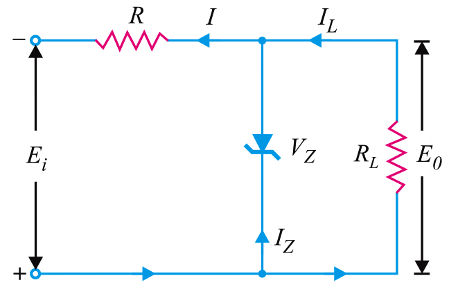
A rectifier with an appropriate filter serves as a good source of d.c. output. However, the major disadvantage of such...
Read more
pi filter Operation
July 18, 2016
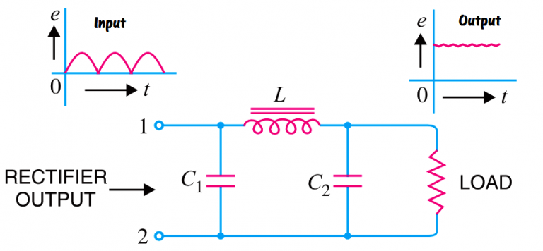
The below Fig shows a typical capacitor input filter or π- filter. It consists of a filter capacitor C1 connected...
Read more
Choke Input Filter Operation
July 18, 2016
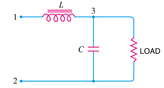
The below Fig. shows a typical choke input filter circuit. It consists of a Choke L connected in series with the...
Read more
Capacitor Filter Operation
July 18, 2016
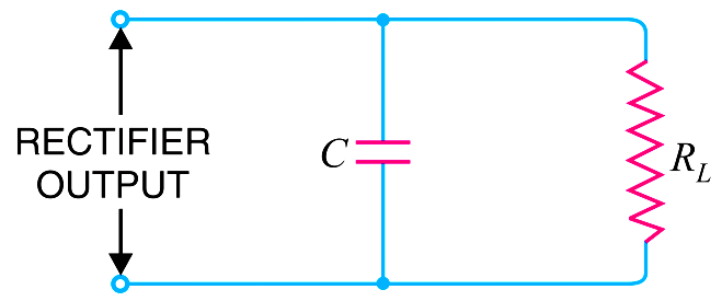
Capacitor filter. Fig. shows a typical capacitor filter circuit. It consists of a capacitor C placed across the rectifier output in...
Read more
What is a Filter Circuit ?
July 18, 2016
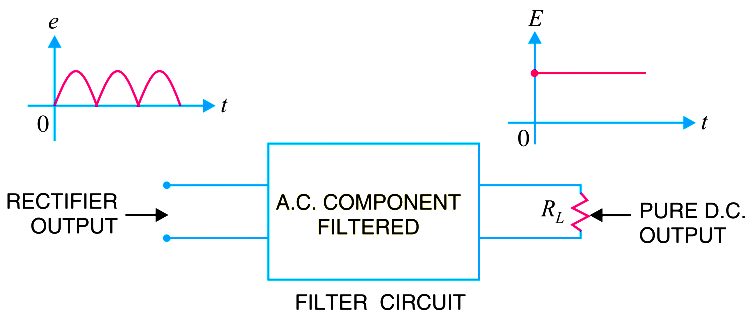
Generally, a rectifier is required to produce pure d.c. supply for using at various places in the electronic circuits. However,...
Read more
Transistor as Amplifier
July 16, 2016
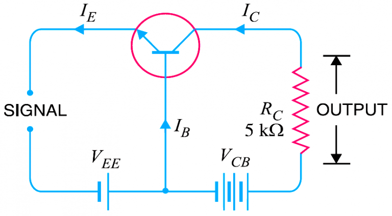
A transistor raises the strength of a weak signal and thus acts as an amplifier. The Below Fig shows the basic circuit...
Read more
Working of NPN Transistor
July 15, 2016
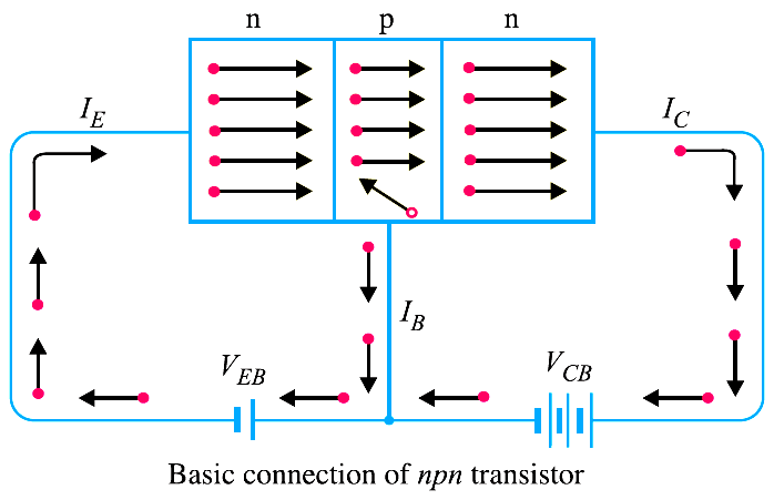
The emitter-base junction of a transistor is forward biased whereas collector-base junction is reverse biased. If for a moment, we...
Read more
Basics of Transistors
July 15, 2016

A transistor consists of two pn junctions formed by *sandwiching either p-type or n-type semicon-ductor between a pair of opposite...
Read more
Comparison of Half wave Rectifiers and Full wave Rectifiers
July 12, 2016
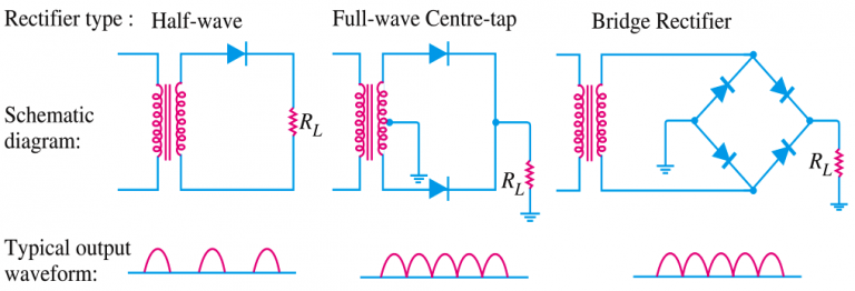
Comparison of Half wave Rectifiers and Full wave Rectifiers
Read more
