The zener diode can be used as a type of voltage regulator for providing stable reference voltages. In this section, you will see how zeners can be used as voltage references, regulators, and as simple limiters or clippers.
Zener Regulation with a Variable Input Voltage
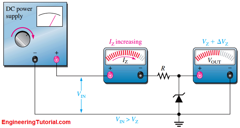
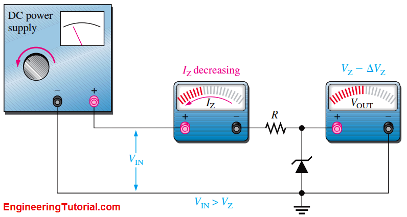
Zener diode regulators can provide a reasonably constant dc level at the output, but they are not particularly efficient. For this reason, they are limited to applications that require only low current to the load. The Below Figure illustrates how a zener diode can be used to regulate a dc voltage. As the input voltage varies (within limits), the zener diode maintains a nearly constant output voltage across its terminals.
However, as VIN changes, IZ will change proportionally so that the limitations on the input voltage variation are set by the minimum and maximum current values (IZK and IZM) with which the zener can operate. Resistor R is the series current-limiting resistor. The meters indicate the relative values and trends.

Fig (a) : As the input voltage increases, the output voltage remains nearly constant (IZK < IZ < IZM).

Fig (b) : As the input voltage decreases, the output voltage remains nearly constant (IZK < IZ < IZM).
Example :
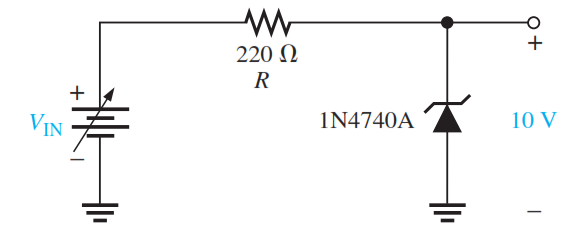
To illustrate regulation, let’s use the ideal model of the 1N4740A zener diode (ignoring the zener resistance) in the circuit shown below. The absolute lowest current that will maintain regulation is specified at Izk which for the 1N4740A is 0.25 mA and represents the no-load current. The maximum current is not given on the datasheet but can be calculated from the power specification of 1 W, which is given on the datasheet. Keep in mind that both the minimum and maximum values are at the operating extremes and represent worst-case operation.


For the minimum zener current, the voltage across the 220 ohms resistor is
Vr = Izk.R = (0.25 mA)(220 ohms) = 55 mV
Since VR = VIN – VZ,
Vin(min) = VR + VZ = 55 mV + 10 V = 10.055 V
For the maximum zener current, the voltage across the 220 ohms resistor is
VR = IzmR = (100 mA)(220 ohms) = 22 V
Therefore,
VIN(max) = 22 V + 10 V = 32 V
This shows that this zener diode can ideally regulate an input voltage from 10.055 V to 32 V and maintain an approximate 10 V output. The output will vary slightly because of the zener impedance, which has been neglected in these calculations.


