While filters can reduce the ripple from power supplies to a low value, the most effective approach is a combination of a capacitor-input filter used with a voltage regulator. A voltage regulator is connected to the output of a filtered rectifier and maintains a constant output voltage (or current) despite changes in the input, the load current, or the temperature. The capacitor-input filter reduces the input ripple to the regulator to an acceptable level. The combination of a large capacitor and a voltage regulator helps produce an excellent power supply.
Most regulators are integrated circuits and have three terminals—an input terminal, an output terminal, and a reference (or adjust) terminal. The input to the regulator is first filtered with a capacitor to reduce the ripple to The regulator reduces the ripple to a negligible amount. In addition, most regulators have an internal voltage reference, shortcircuit protection, and thermal shutdown circuitry. They are available in a variety of voltages, including positive and negative outputs, and can be designed for variable outputs with a minimum of external components. Typically, voltage regulators can furnish a constant output of one or more amps of current with high ripple rejection.
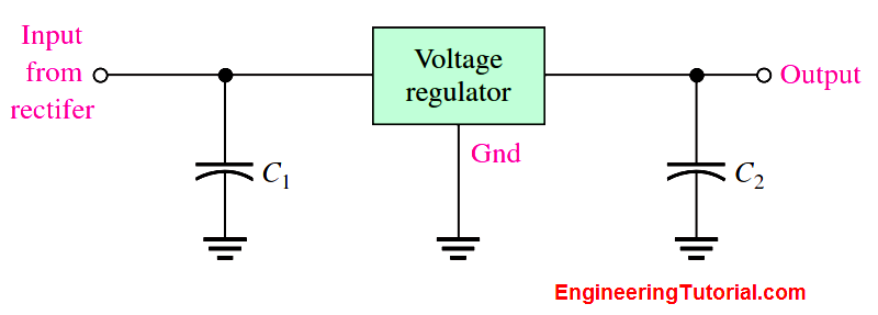
Three-terminal regulators designed for fixed output voltages require only external capacitors to complete the regulation portion of the power supply, as shown in Below Figure.Filtering is accomplished by a large-value capacitor between the input voltage and ground.An output capacitor (typically ) is connected from the output to ground to improve the transient response. 0.1 mFto1.0mF 610%.

Fig : A voltage regulator with input and output capacitors.
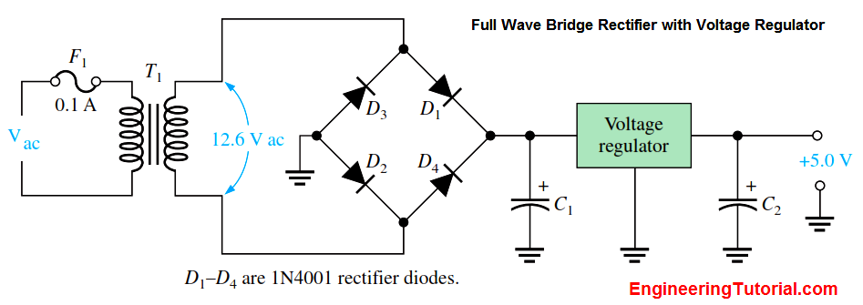
A basic fixed power supply with a +5 V voltage regulator is shown in Below Figure. Specific integrated circuit three-terminal regulators with fixed output voltages are available in the market.

Fig : A basic +5.0 V regulated power supply.
Percent Regulation
The regulation expressed as a percentage is a figure of merit used to specify the performance of a voltage regulator. It can be in terms of input (line) regulation or load regulation.
Line Regulation
The line regulation specifies how much change occurs in the output voltage for a given change in the input voltage. It is typically defined as a ratio of a change in output voltage for a corresponding change in the input voltage expressed as a percentage.

Load Regulation
The load regulation specifies how much change occurs in the output voltage over a certain range of load current values, usually from minimum current (no load, NL) to maximum current (full load, FL). It is normally expressed as a percentage and can be calculated with the following formula:

where VNL is the output voltage with no load and VFL is the output voltage with full (maximum) load.


