The safe operating area determines the current and voltage boundary within which the device can be operated without destructive failure.
There are two SOAs:
Forward Biased Safe Operating Area (FBSOA)
Reverse Biased Safe Operating Area (RBSOA)
It is recommended to read about power MOSFET structure for proper understanding of the Power MOSFET Safe Operating Area.
Some of the facts about Power MOSFET is given below:
- Power MOSFET has three terminals called Drain, Source and Gate.
- It is a voltage controlled device.
- It is a unipolar device so its operation depends upon the flow of majority carriers only.
- The gate circuit impedance very high.
- So the control signal(gate voltage) required to turn on the MOSFET is lesser than required control signal for the BJT.
- There is no second breakdown problem in this device.
- MOSFET has positive temperature coefficient, so thermal runaway problem will not happen.
The Safe Operating Area of Power MOSFET is given here:
- All the maximum voltage and current ratings and power dissipation are conveniently brought together in the safe operating area diagram.
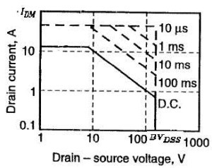
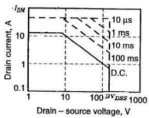
- This is based on logarithmic plot of drain current against Drain-to-Source voltage as shown in the figure.
- The solid line shows the bounding values for DC operation.
- When the MOSFET is operating for a short intervals, the power dissipation is lesser than the continuous operation.
- So the Power MOSFET Safe Operating Area may be extended as shown in the figure by the dotted line.

- The factors that determine the SOA of the Power MOSFET are
- The maximum drain current IDM
- The breakdown voltage BVDSS
- The internal junction temperature Tj ( it is governed by the power dissipation in the device)
- Note that there is no secondary slope on the SOA curves, indicating the absence of second breakdown. We can observe the secondary breakdown problem in BJTs SOA, which is the major drawback or the Power BJT.
- As the MOSFET does not have second breakdown limit, the Power MOSFET Safe Operating Area (SOA) is large. It means snubber circuits are not required to protect the device in most situations.
- Because the MOSFET is a majority-carrier device, its on-state resistance has a positive temperature coefficient.
- If localized and potentially destructive heating occurs within the device the positive temperature coefficient effect of resistance forces local current concentration to be uniformly distributed across the total area.
- There is no difference between forward-bias and reverse-bias SOAs for the MOSFET. They are identical.
- The MOSFET will work properly and the device will not degrade when it works within the Safe Operating Limits (SOA) of the device.
- To select a MOSFET for a particular application, following parameters have to be considered from the device datasheet
- Maximum Drain to Source voltage (VDSS)
- On-state drain to source resistance RDS(ON)
- Drain Current ID
- Gate to source Voltage VGS
- Reverse recovery time Trr
- Gate charge QG
- Power Dissipation PD
- Out of these selection parameters, we can get the limits of maximum drain to source voltage and drain current from the SOA graph of the device.


