Diode Biased Limiters/Clippers
First read basics of Diode Clippers. Click Here to read
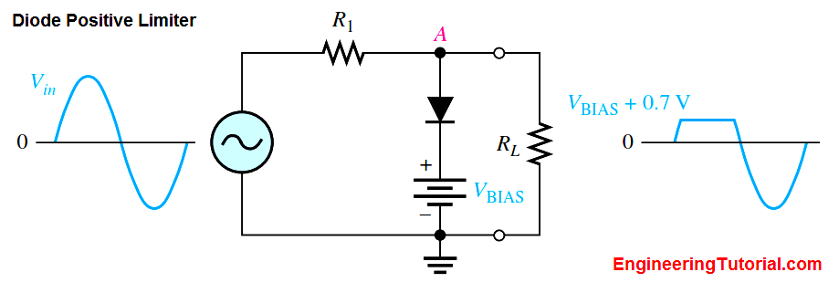
The level to which an ac voltage is limited can be adjusted by adding a bias voltage, VBIAS, in series with the diode, as shown in Below Figure. The voltage at point A must equal VBIAS + 0.7 V before the diode will become forward-biased and conduct. Once the diode begins to conduct, the voltage at point A is limited to VBIAS + 0.7 V so that all input voltage above this level is clipped off.

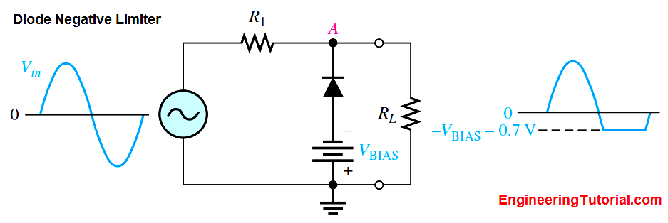
To limit a voltage to a specified negative level, the diode and bias voltage must be connected as in Below Figure. In this case, the voltage at point A must go below -VBIAS – 0.7 V to forward-bias the diode and initiate limiting action as shown.

By turning the diode around, the positive limiter can be modified to limit the output voltage to the portion of the input voltage waveform above VBIAS – 0.7 V, as shown by the output waveform in Figure (a). Similarly, the negative limiter can be modified to limit the output voltage to the portion of the input voltage waveform below -VBIAS + 0.7 V, as shown by the output waveform in part (b).

Fig a : Clipper Circuit during Positive Half cycle

Fig b : Clipper Circuit during Negative Half cycle
Diode Limiter Application
Many circuits have certain restrictions on the input level to avoid damaging the circuit. For example, almost all digital circuits should not have an input level that exceeds the power supply voltage. An input of a few volts more than this could damage the circuit. To prevent the input from exceeding a specific level, you may see a diode limiter across the input signal path in many digital circuits.


