Over Heat Of Resistor
Resistors are probably the most robust of all electronic components, with high reliability and a long life. It is difficult to damage a resistor by overheating it with a soldering iron.
The wattage rating of a resistor does not necessarily mean that it should be used to dissipate that amount of power on a constant basis. Small resistors (1/4 watt or less) can overheat just as easily as big ones. Generally speaking, it is safe practice not to exceed 75% of a resistor’s power rating on a constant basis.
Overheating is predictably more of a problem for power resistors, where provision must be made for heat dissipation. Issues such as component crowding should be considered when deciding how big a heat sink to use and how much ventilation. Some power resistors may function reliably at temperatures as high as 250 degrees Centigrade, but components near them are likely to be less tolerant and plastic enclosures may soften or melt.
Resistor Affected An Noise
The electrical noise introduced by a resistor in a circuit will vary according to the composition of the resistor, but for any given component, it will be proportional to voltage and current. Lownoise circuits (such as those at the input stage of a high-gain amplifier) should use low-wattage resistors at a low voltage where possible.
Resistor Affected An Inductance
The coiled wire of a wire-wound resistor will be significantly inductive at low frequencies. This is known as parasitic inductance. It will also have a resonant frequency. This type of resistor is unsuitable for applications where frequency exceeds 50KHz.
Inaccuracy Calculations Of Resistor Value
When using resistors with 10% tolerance, imprecise values may cause greater problems in some applications than in others. In a voltage divider, for instance, if one resistor happens to be at the high end of its tolerance range while the other happens to be at the low end, the voltage obtained at the intersection of the resistors will vary from its expected value.
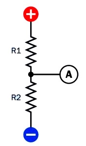
In a DC circuit, a pair of resistors may be placed in series to function as a voltage divider. The voltage measured at A will be lower than the supply voltage, but above ground potential.
Using the schematic shown in the figure above, if R1 is rated for 1K and R2 is rated for 5K, and the power supply is rated at 12VDC, the voltage at point A should be:
V = 12 * (( 5 / (5 + 1)) = 10
However, if R1 has an actual value of 1.1K and R2 has an actual value of 4.5K, the actual voltage obtained at point A will be:
V = 12 * (( 4.5 / (4.5 + 1.1)) = 9.6
If the resistors are at opposite ends of their respective tolerance ranges, so that R1 has an actual value of 900Ω while the lower resistor has an actual value of 5.5K, the actual voltage obtained will be:
V = 12 * (( 5.5 / (5.5 + 0.9)) = 10.3
The situation becomes worse if the two resistors are chosen to be of equal value, to provide half of the supply voltage (6 volts, in this example) at their intersection. If two 5K resistors are used, and the upper one is actually 4.5K while the lower one is 5.5K, the actual voltage will be:
V = 12 * (( 5.5 / (4.5 + 5.5)) = 6.6
Whether this variation is significant will depend on the particular circuit in which the voltage divider is being used.
Common through-hole resistors may occasionally turn out to have values that are outside their specified tolerance range, as a result of poor manufacturing processes. Checking each resistor with a meter before placing it in a circuit should be a standard procedure.
When measuring the voltage drop introduced by a resistor in an active circuit, the meter has its own internal resistance that will take a proportion of the current. This is known as meter loading and will result in an artificially low reading for the potential difference between the ends of a resistor. This problem becomes significant only when dealing with resistors that have a high value (such as 1M), comparable with the internal resistance of the meter (likely to be 10M or more).
Wrong Values (Incorrect Instalation Of Resistor)
When resistors are sorted into small bins by the user, errors may be made, and different values may be mixed together. This is another reason for checking the values of components before using them. Identification errors may be nontrivial and easily overlooked: the visible difference between a 1 megohm resistor and a 100Ω resistor is just one thin color band.


