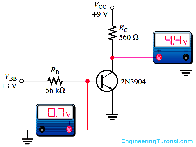
Several faults can occur in a simple transistor bias circuit. Possible faults are open bias resistors, open or resistive connections, shorted connections, and opens or shorts internal to the transistor itself. The above Figure is a basic transistor bias circuit with all voltages referenced to ground.
The two bias voltages are VBB = 3 V and VCC = 9 V. The correct voltage measurements at the base and collector are shown. Analytically, these voltages are verified as follows. A bDC = 200 is taken as midway between the minimum and maximum values of hFE given on the datasheet for the 2N3904 (Note : Download transistor datasheet for reference). A different hFE (bDC), of course, will produce different results for the given circuit.

