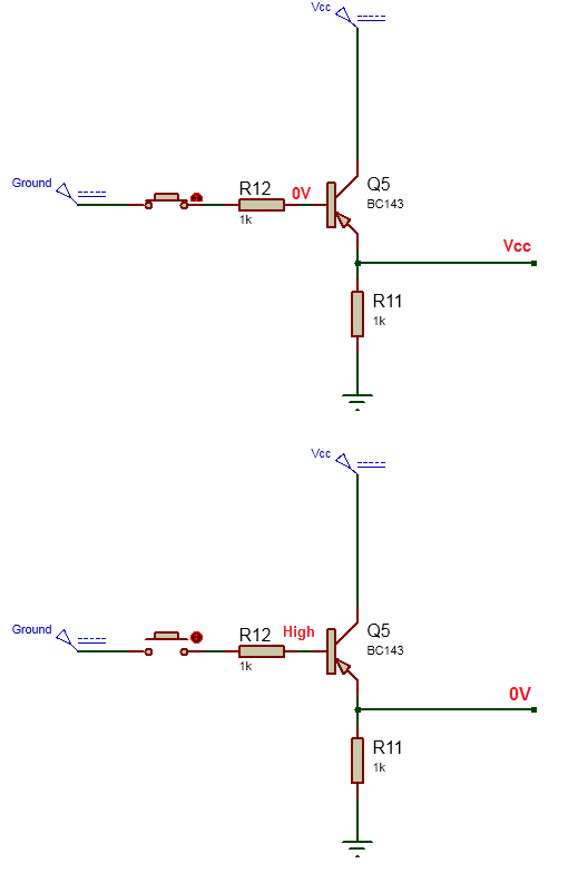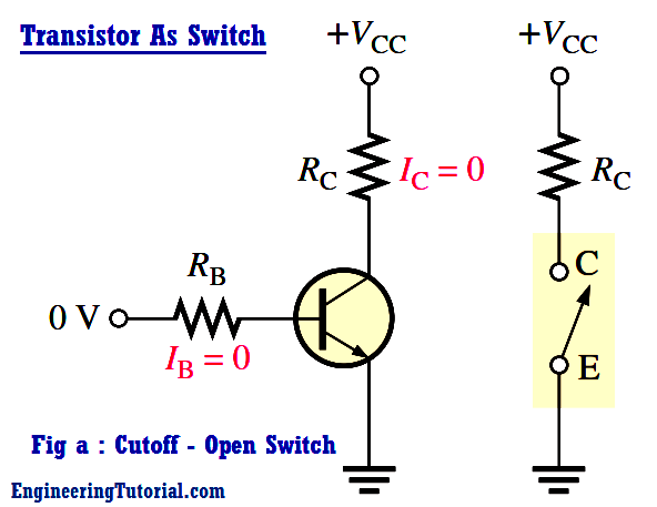
The below Figure illustrates the basic operation of a BJT as a switching device. In part (a), the transistor is in the cutoff region because the base-emitter junction is not forward-biased. In this condition, there is, ideally, an open between collector and emitter, as indicated by the switch equivalent.

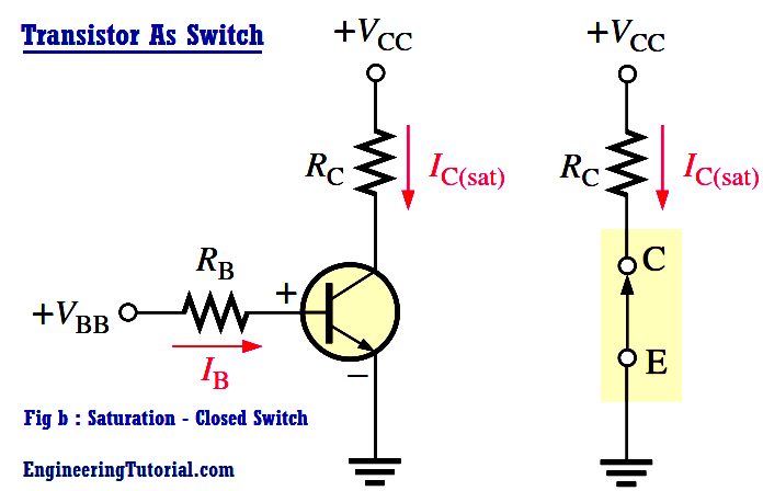
In part (b), the transistor is in the saturation region because the base-emitter junction and the base-collector junction are forward-biased and the base current is made large enough to cause the collector current to reach its saturation value. In this condition, there is, ideally, a short between collector and emitter, as indicated by the switch equivalent. Actually, a small voltage drop across the transister of up to a few tenths of a volt normally occurs, which is the saturation voltage, VCE(sat).

Conditions in Cutoff : As mentioned before, a transistor is in the cutoff region when the base-emitter junction is not forward-biased. Neglecting leakage current, all of the currents are zero, and VCE is equal to VCC.
VCE(cutoff) = VCC
Conditions in Saturation : As you have learned, when the base-emitter junction is forward-biased and there is enough base current to produce a maximum collector current, the transistor is saturated. The formula for collector saturation current is

Since VCE(sat) is very small compared to VCC, it can usually be neglected.
The minimum value of base current needed to produce saturation is

Normally, IB should be significantly greater than IB(min) to ensure that the transistor is saturated.
Related Articles :
Engineering Tutorial Keywords:
- Фототранзистор KINGBRIGHT
