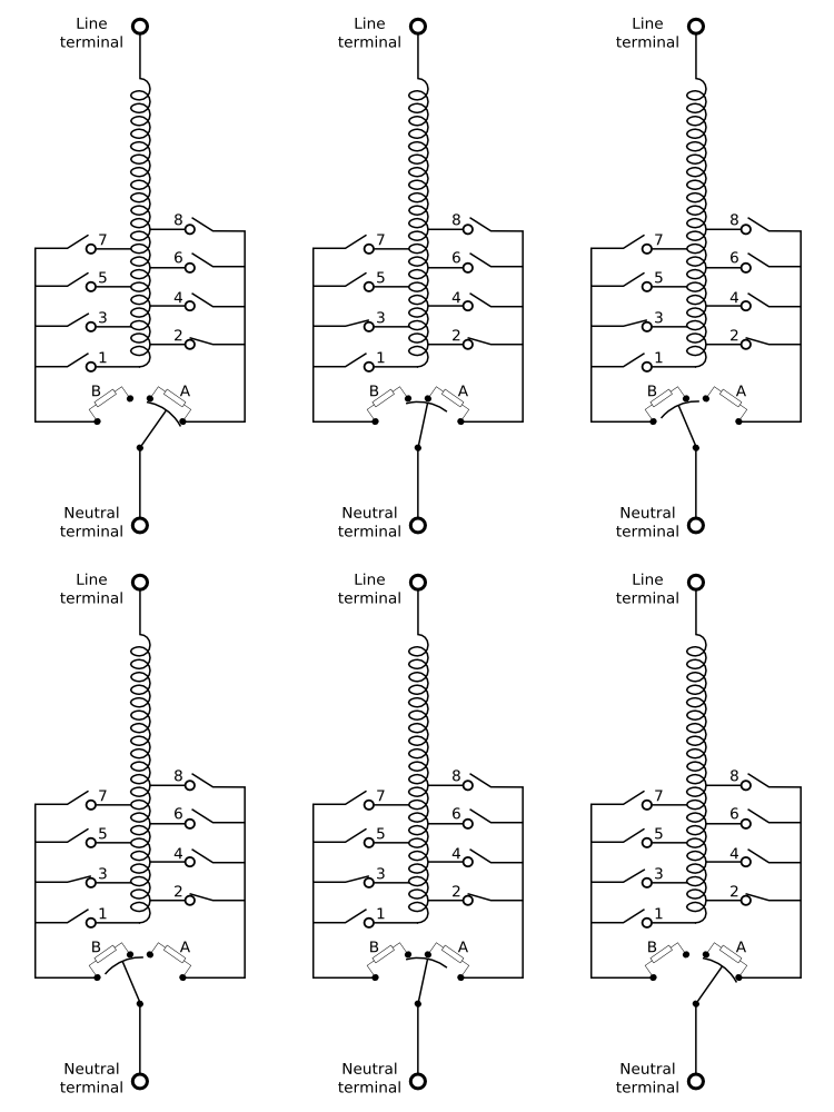
Animation of an on-load transformer tap changer, illustrating how taps can be selected without either interrupting supply or short-circuiting winding turns.
The tap changer starts at tap position 2, with load supplied directly via the right hand connection. Diverter resistor A is short-circuited, diverter B is unused.
If the tap changer is moved to tap 3, the following sequence occurs:
- Switch 3 closes, an off-load operation.
- Rotary switch turns, breaking one connection and passing load current through diverter resistor A.
- Rotary switch continues to turn, connecting between contacts A and B. Load now supplied via diverter resistors A and B, winding turns bridged via A and B.
- Rotary switch continues to turn, breaking contact with diverter A. Load now supplied via diverter B alone, winding turns no longer bridged.
- Rotary switch continues to turn, shorting diverter B. Load now supplied directly via left hand connection. Diverter A is unused.
- Switch 2 opens, an off-load operation.
The animation then shows the tap changer returning to its starting position by reversing the above sequence of operations.
Related Articles :
Engineering Tutorial Keywords:
- content
- three phase tap changer diagram
