What is a transformer?
Transformer is a static electrical device which transfers power from one circuit to another circuit without any physical contact. The main aim of this transformer is that the output power of the transformer is same as output power. The term static indicates that it does not contain any rotating part in it.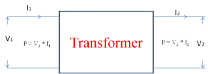 In addition to the power transfer it also acts as a parameter control device or parameter changing device. The above figure shows that the input and output are same where as cases the voltage and currents may not be same. i.e. the voltage and current at the output can be changed by varying output windings to get the desired parameter at the output. Like as in step up transformer the voltage is stepped up i.e. the output is high compared to input voltage but the power ratio is same.
What is transformer working principle?
Transformer works on the principle of Faraday’s electromagnetic induction principle where varying magnetic field produces an EMF in the electric coil. Basically it is the combination of two laws i.e. in primary side the varying current produces a varying magnetic field (electromagnetism) and this magnetic flux lines are cut by the adjacent secondary coil (induction principle) and EMF will be induced.
Es = Ns (dΦ/dt)
Ep = Np(dΦ/dt)
 Electro Magnetic field introduction
What is an equivalent circuit of a transformer?
Transformer consists of two coils called primary and secondary which will have inductance and as well as small resistance.
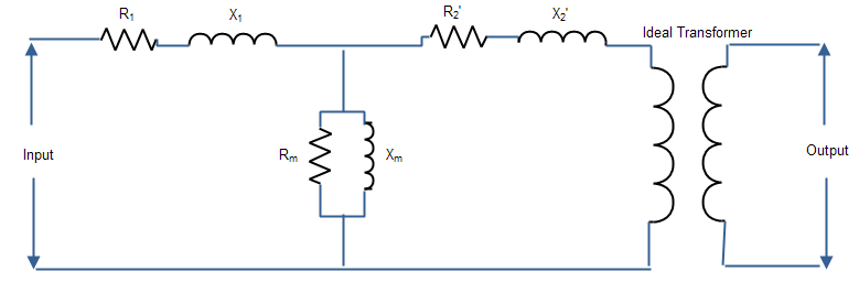
In the above equivalent circuit
R1= Primary coil resistance
X1= Primary coil inductance
R2’= Secondary equivalent coil resistance
X2’= Secondary equivalent coil inductance
Rm = Magnetizing resistance
Xm= Magnetic inductance.
The magnetizing components in the transformer indicate the losses of power to magnetize the core which acts as a magnetic flux transmission media. To simplify the circuit the secondary components brought to primary side which are R2’ and X2’ where
R2’= R2/N2
X2’= X2/N2
Where N is the turns ration between primary and secondary.
N= N1/N2
N1= primary Inductor coil number of turns
N2 = Secondary number of turns.
What is a transformer core?
Transformer core is an important component of an amplifier as it acts a bridge for the magnetic flux between primary and secondary coils. There are two types of cores air and iron. In air core transformer the reluctance offered for the flow of magnetic flux is high compared to iron core so more flux transmission from primary to secondary hence more efficiency. The cost is a bit high because of the iron in iron core transformer.
What is the difference between transformer and amplifier?
Amplifier: An electronic device which increases or boosts the power of the signal is called is an amplifier. I.e. both quantities of the signal (voltage and current), increases in amplifier. If it is voltage amplifier also there will not be decrease in current.
Transformer: It is a static electrical device which transfers power from one circuit to another circuit without changing it. Even though the signal quantities (voltage and current) can be boosted at the output, it cannot acts as amplifier because if one of the quantities is boosted at the output the other quantity is reduced. So the power is same.
What is difference between induction motor and transformer?
The main difference between induction motor and transformer is that transformer is a static machine and motor is an rotating machine. The secondary winding in induction motor is wounded on rotor to convert primary power in to rotational force. Where as in transformer there is no conversion of energy and hence no work done.
What is auto transformer?
Auto transformer is one type of transformer which shares one winding as primary and secondary coil. This is also called as single coil transformer where at the input and output leads are from same coil. It is designed to use for small voltage changing applications i.e. it can increase or decrease the output voltage a small bit because of one coil sharing.
What are the advantages and disadvantages of auto transformer?
Advantages:
- Smaller in size (consists of only one winding)
- Cost is less
- Better use in smaller applications
Disadvantages:
- There is no isolation between primary and secondary.
- Fault current can damage the entire circuit.
Why taping is connected to high voltage side?
The transformer taping connected generally to high voltage winding side because
- The high voltage winding is wounded over low voltage winding and accessing of that winding is easy compared to low voltage winding.
- In high voltage side, the current is less and the flash over during tap changing is less in the case of on-load tap changer.
Why high voltage winding is wounded over low voltage winding?
In low voltage winding the current flowing is high compared to high voltage winding ad hence I2R (core losses) losses are high which produces high heat. So, the low winding is wounded inside to avoid this heating affect to the transformer casing because of the large gap. Till that heat reaches the cooling medium removes the heat.
What are the methods of transformer cooling?
Transformer cooling is used to remove the heat produced in it.
Dry type transforms:
- Self-air cooled (up to 3 MVA):
- Forced Air Cooled (Up to 15 MVA):
Oil immersed type:
- Oil-Immersed Self cooled:
- Oil-Immersed forced air cooled:
- Oil-Immersed water cooled:
What is step-up transformer?
Step-up transformer is a transformer whose secondary voltage is higher than the primary voltage. To do this the secondary coil tunes are wounded high compared to the primary coil turns. This transformer has main application in power plants where the generation voltage has to be stepped up to transmit for long distance.
What step-down transformer?
Step down transformer is a voltage down transformer where the secondary voltage is less compared to primary voltage. This is achieved by providing lower turns of coil in secondary compared to primary. The main application of this type of transformer is in distribution side where as the transmitted high voltage has to be stepped down to distribute it for households purposes.
What is voltage transformer?
Voltage transformer is sometimes called as potential transformer which is used to measure the voltage of the line. Basically it is a step down transformer which reduces the line voltage to minimum voltage (safe voltage) which a voltage meter can measure. It also isolates the high voltage line and metering circuit to safe guard the metering circuit during a fault condition.
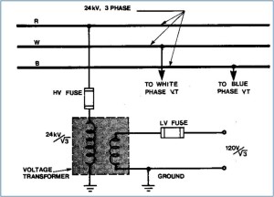 Voltage Transformer connection diagram
Voltage transformers are usually connected between line and ground in which it is protected with the fuses.
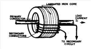
What is current transformer?
Current transformer is an instrument transformer used to measure the current flowing through the windings. Normally primary winding will be single wire and secondary will be many turns so the secondary measuring current will be less. The current transformers can be used for metering purpose or for protection purpose. The output of the CT will be normally 5 or 10 amps. So according to the turn’s ratio will be arranged. Figure shows the arrangement of CT where the primary conductor carrying current induces the magnetic flux in secondary turns to produce the respective turns.
 What is power transformer?
Power transformer is a transformer used to transmit the power from the generating station to the destination. These are big in size and used for large power applications. These are typically used between the two ends of transmission lines to step-up the voltage at the generating end of transmission line and to step down the voltage at the receiving end of the transmission side.
What is a distribution transformer?
Distribution transformer is basically a step down transformer which decreases the transmission high voltage in to low voltage. As the name specifies it distributes the power for various house and industrial purposes with a reduced end user voltage. So the load fluctuations are very high on these transformers. These are normally operated less power compared to power transformers. These transformers are also provides isolation between primary and secondary to limit the secondary fault current. The power should be passed through the distribution transformer before supplying it to the end user.
What are the differences between power transformer and distribution transformer?
| Power transformer | Distribution transformer | |
| Power transmitted | High | low |
| Voltage | Step up or Step down | Step Down |
| Size | Large | small |
| Application | Transmission lines and generating stations | To transmit the power to end user. |
| Load fluctuations | Less (constantly operated) | High (as the loads will be disconnected and connected) |
| Tap changer | Off-load tap changer | On-load tap changer to encounter the load fluctuations |
| Losses | Heat losses are high because of high rated current | Heat losses are low because of low rated currents |
| Place | Indoor (Generally) | Outdoor (near end user) |
Advantages of iron core transformer?
- The magnetic reluctance of iron is less so that it allows more flux through it.
- Efficiency is high compared to air core
- Heat losses are less.
- It is used for low frequencies (<10KHz).
Advantages of air core transformer?
- It is used for the high frequencies (>10KHz).
- Core saturation problem is not there in air core.
- Simple in construction.
- Size is less because of no iron.
- Cost is less.
- Magnetization losses are less in air core compared to iron core.
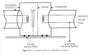
What is isolation transformer?
Isolation transformer is a static machine used to isolate the two circuits and provides a magnetic coupling between two circuits. It avoids the coupling losses and provides better safety to the both the circuits from the fault in other circuit. As the name specifies it provides only isolation, so the primary and secondary windings turns are same to ensure that there is no change in signal quantities like voltage and current.
What is transformer tap changer?
A tap changer is a device used to change the primary or secondary voltage of the transformer by changing the turn’s ratio without remodeling the transformer. The primary function of the transformer is it removes or connects some portion of the winding either load side or source side. The importance of tap changer is maintaining the load side voltage constant irrespective of load variations. There are two types of tap changer one is off-load changer and on-load tap changer.
What is off-loading tap changer?
Off-load tap changer works on the principle “Break before Make” which breaks the current flow and makes the new tap connection. So this tap changer works when there is no current flow in the transformer windings i.e. it cannot work even when the transformer is energized because it can break the magnetizing current. It is nowadays called as De-energizing tap changer instead of No-load or Off-load tap changer.
What is on-load tap changer?
On-load tap changer is device which operates and changes the tap connection even when the transformer is supplying the load. This works on the principle of “Make before Break” which makes the new circuit before breaking the old tap circuit. It is very important invention that it can keep the transformer load voltage irrespective of load varying during operation itself.
What is the difference between isolating and shielding transformer?
Isolating transformer: This transformer is used to provide isolation between primary and secondary to protect the winding from the faults.
Shielding transformer: In high power applications the isolation transformers are provided with shielding plates between primary and secondary to reduce the high frequency noise in the transformer. When high frequency surge pulse is introduced in system, the capacitor near primary winding creates a short circuit path and diverts this pulse to the ground.
 Shielding Transformer
What is the difference between instrument and protection transformer?
Instrument transformer is used to measure the signal parameters (voltage and current) to indicate in the meters (voltage and current) where as protection transformer measuring signal is used for relay operation for protection of transformer.
Instrument transformer can be operated at near core saturation limit as the meter indicates up to rated values but the protection transformer should be available for 50 % higher than rated current so these should be operated below the core saturation.
The accuracy should be high for Instrument transformers where as in protection it can be somewhat less.
What is the impact if the 60 Hz transformer is operated at 50 Hz transformer?
The 50 Hz transformer can be operated at 60Hz for some cases but 60 Hz transformer cannot be operated for 50Hz. Because as the frequency decreases the flux increase for a constant voltage.
Fi = volateg/flux
The increase in flux leads to core saturation.
What happens if the input voltage of the transformer is higher than name plate?
The transformer cannot be operated more than 10% higher than the rated voltage because if the primary is high therefore secondary also increases which leads to increase in power rating of a transformer. This increases the heat losses and may damage the transformer. The second one is that if the voltage is increased beyond the rated value at rated frequency then the flux will increased in the transformer
Flux = Voltage/frequency
The increase in flux leads to core saturation and heating affect and degrades the transformer performance.
What are the losses in transformer?
In power transmission from primary and secondary, there are losses in the transformer which are bases on load of the transformer i.e. No-load losses and Load Losses.
2) Pt = PNL + PLL
Where.
Pt = Total Losses in the transformer
PN L = No-load losses in the transformer
PLL = Load losses in the transformer.
No load losses:
1) Hysteresis losses in the core lamination
2) Eddy current losses in the core lamination
3) Dielectric losses in the transformer components during excitation.
4) I2R losses due to no-load current in the primary and secondary windings.
Load losses:
1) Primary winding copper loss (I12R1)
2) Secondary winding copper loss (I22R2)
What is a three phase transformer?
The three phase transformer consists of three primaries and three secondary winding with the same magnetic coupling as in the normal transformer. Where as in this transformer the power transmitted is much more compared to single phase transformer. It consists three iron core legs on which the windings are mounted. These can be delta connected or star connected winding depending up on their application.
What is single phase transformer?
Single phase transformer is a normal transformer with one primary and one secondary winding which are magnetically coupled. This is normally used for distribution purposes primarily household where the loads are single phase loads. It consists of two terminals phase and neutral. The power transmission is less and construction and size of single phase transformer is less compared to three phase transformer.
Differences between single phase and three phase transformer?
| Parameter | Single phase | Three phase |
| Windings | One set of primary and secondary windings | Three sets of primary and secondary windings which are connected in Delta or Star arrangement. |
| Power transmission | Less because of one phase | Power transmission is high as the three phases combinely transmits high power |
| Application | Distribution purpose | Transmission lines and power generating stations |
| Cost | Less | high |
| Size | Less | high |
Advantages of three phase systems
- Three phase motors for a given horsepower are smaller in physical size compared to single phase.
- Smaller conductors are required to carry the same amount of power compared to single phase.
- Three phase motors are self-starting while single phase motors require an auxiliary start winding.
- Three phase motors have better power factor compared to single phase motor.
- Rectified Three phase signal gives less ripple factor compared single phase rectifier.
- Requires less copper compared to single phase to transmit the same power.
- High efficiency compared to single phase motor.
What is transformer regulation?
Transformer regulation is defined as the percentage change in output voltage from no-load to full load with respect to full load. It can also measured with respected to no-load voltage where as in the first case it is called as regulation up and in second case it is called as regulation down.
% regulation = No-load Voltage – Full load voltage/ full load voltage * 100;
Under no load condition the induced voltage E2 is presented at the output terminals and when the transformer is loaded due to drop across the reactance it changes to V2. So the expression for transformer regulation is
% regulation = (E2 –V2)/V2 * 100.
What is transformer impedance?
The impedance of the transformer is the combination of resistance and reactance of the primary and secondary winding coils.
Z1= R1+X1
Z2= R2+X2
Due to this impedance there will be voltage drop in the both primary and secondary windings.
What are the name plate details of transformer?
The following details shows the typical name plate details of a transformer
Power rating (1000 KVA) : It indicates that the transformer is able to supply 1000 KVA of load without any problem.
H.V rating (21KV): This is the maximum high voltage side voltage with it can withstand. If the applied voltage is higher than 10% of rated voltage then transformer core saturation may occur.
L.V rating (6.6KV): This is the rated secondary line voltage of the transformer.
Frequency (60Hz): The rated frequency of the transformer with it can operated. The transformer can be operated above the rated frequency but it cannot be operated below.
%impedance: It indicates the amount of voltage drop from the no-load current to full load current.
Tap voltages: This parameter specifies the rated voltage for each tap that the transformer can provide.
Type of transformer: power transformer, distribution transformer, instrumentation transformer etc.
Winding connection diagram: This diagram shows the primary and secondary winding connection diagram.
Cooling class (ONAF): This indicates of type of cooling used in transformer. For example ONAF indicates that it is Oil Natural and Air Forced type cooling.
Rated temperature (600): The maximum rated temperature that the transformer can be operated without any heating.
In-addition to the above the name plate also contains about weight of the transformer, volume of the oil, type of insulating material etc.
Related Articles :
Engineering Tutorial Keywords:
- interview questions about transformer
- interview questions of transformer
- interview questions on transformer