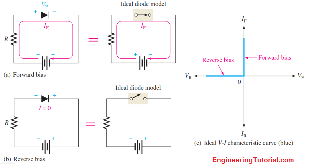
The ideal model of a diode is the least accurate approximation and can be represented by a simple switch. When the diode is forward-biased, it ideally acts like a closed (on) switch, as shown in Figure (a). When the diode is reverse-biased, it ideally acts like an open (off) switch, as shown in part (b). Although the barrier potential, the forward dynamic resistance, and the reverse current are all neglected, this model is adequate for most troubleshooting when you are trying to determine if the diode is working properly.

In Figure c), the ideal V-I characteristic curve graphically depicts the ideal diode operation. Since the barrier potential and the forward dynamic resistance are neglected, the diode is assumed to have a zero voltage across it when forward-biased, as indicated by the portion of the curve on the positive vertical axis.
VF = 0 V
The forward current is determined by the bias voltage and the limiting resistor using Ohm’s law.

Since the reverse current is neglected, its value is assumed to be zero, as indicated in Figure (c) by the portion of the curve on the negative horizontal axis.
IR = 0 A
The reverse voltage equals the bias voltage.
VR = VBIAS
You may want to use the ideal model when you are troubleshooting or trying to figure out the operation of a circuit and are not concerned with more exact values of voltage or current.


