Half-Wave Rectifier Operation

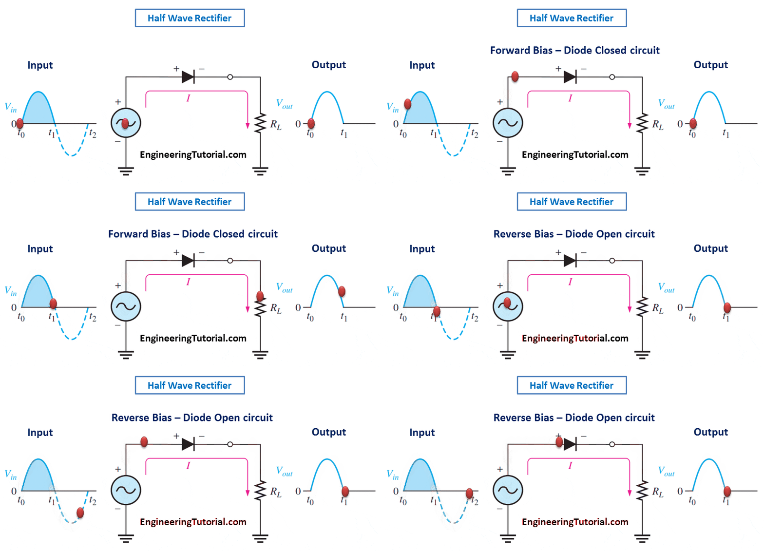
The below Figure illustrates the process called half-wave rectification. A diode is connected to an ac source and to a load resistor, RL, forming a half-wave rectifier. Keep in mind that all ground symbols represent the same point electrically. Let’s examine what happens during one cycle of the input voltage using the ideal model for the diode. When the sinusoidal input voltage (Vin) goes positive, the diode is forward-biased and conducts current through the load resistor, as shown in part (a). The current produces an output voltage across the load RL, which has the same shape as the positive half-cycle of the input voltage.

(a) During the positive alternation of the AC input voltage, the output voltage looks like the positive half of the input voltage. The current path is through ground back to the source.

(b) During the negative alternation of the input voltage, the current is 0, so the output voltage is also 0.

When the input voltage goes negative during the second half of its cycle, the diode is reverse-biased. There is no current, so the voltage across the load resistor is 0 V, as shown in Figure (b). The net result is that only the positive half-cycles of the ac input voltage appear across the load. Since the output does not change polarity, it is a pulsating dc voltage output as shown in above figure.
Average Value of the Half-Wave Output Voltage
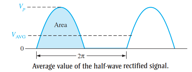
The average value of the half-wave rectified output voltage is the value you would measure on a dc voltmeter. Mathematically, it is determined by finding the area under the curve over a full cycle, as illustrated in Below Figure, and then dividing by 2p, the number of radians in a full cycle. The result of this is expressed in below Equation , where Vp is the peak value of the voltage. This equation shows that VAVG is


Effect of the Barrier Potential on the Half-Wave Rectifier Output
When the practical diode model is used with the barrier potential of 0.7 V taken into account, this is what happens. During the positive half-cycle, the input voltage must overcome the barrier potential before the diode becomes forward-biased. This results in a half-wave output with a peak value that is 0.7 V less than the peak value of the input. The expression for the peak output voltage is
![]()
Peak Inverse Voltage (PIV)
The peak inverse voltage (PIV) equals the peak value of the input voltage, and the diode must be capable of withstanding this amount of repetitive reverse voltage. For the diode, the maximum value of reverse voltage, designated as PIV, occurs at the peak of each negative alternation of the input voltage when the diode is reverse-biased. A diode should be rated at least 20% higher than the PIV.
![]()


The animation of the halfwave rectifier circuit in reverse bias condition is incorrect. The terminals should have their polarity reversed and the ball should come out of the bottom terminal add travel through the resistor up to the diode where it will be blocked.