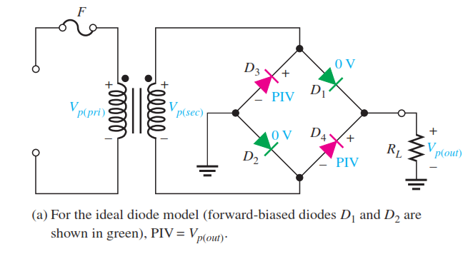
Peak Inverse Voltage Let’s assume that D1 and D2 are forward-biased and examine the reverse voltage across D3 and D4. Visualizing D1 and D2 as shorts (ideal model), as in Figure (a), you can see that D3 and D4 have a peak inverse voltage equal to the peak secondary voltage. Since the output voltage is ideally equal to the secondary voltage,
PIV = Vp(out)
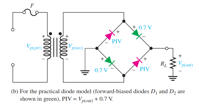
If the diode drops of the forward-biased diodes are included as shown in Figure (b), the peak inverse voltage across each reverse-biased diode in terms of Vp(out) is
![]()
The PIV rating of the bridge diodes is less than that required for the center-tapped configuration. If the diode drop is neglected, the bridge rectifier requires diodes with half the PIV rating of those in a center-tapped rectifier for the same output voltage.


Fig : Peak inverse voltages across diodes D3 and D4 in a bridge rectifier during the positive half-cycle of the secondary voltage.


