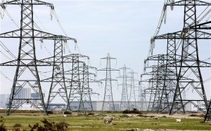
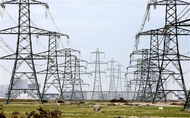
Electricity distribution is the final stage in the delivery of electricity to end users.A distribution system’s network carries electricity from the transmission system and delivers it to consumers. Typically, the network would include medium-voltage (1kV to 72.5kV) power lines, substations and pole-mounted transformers, low-voltage (less than 1 kV) distribution wiring and sometimes meters.For economical generation of power large generating stations are used. Capacities of individual generating sets have gone up recently. Generating sets in the range of 10 MW, 210 MW and 500 MW are being manufactured in many countries. Generating station are now not necessarily located at load centers.
In fact other factors like availability of fuel and water play more dominating role in the selection of sites for thermal stations. Hydro stations are obviously located only at the sites where water is available at sufficient head. A vast network of transmission system has been created so that power generated at one station may be fed to grid system and may be distributed over large areas and number of states. The transmission and distribution system comprises a network of three-phase circuits with transforming and or switching substations at the various junctions. The parts of a transmission and distribution network maybe grouped as given below.
TRANSMISSION:
Several generating stations can be inter connected. The main advantages are :
(i) reduction in the number of spare plants required as one station can assist the other at the time of emergency.
(ii) during light loads one station or some generators can be shut off, thus affecting operational economy.
Primary transmission:
High voltages of the order of 66 kV 132 kV 220 kV and 400 kV are used for transmitting power by 3 phase 3 wire overhead system. This is supplied to substations usually at the out skirts of major distribution center or city.
Secondary transmission:
The primary voltage is reduced to low values of the order of 3.3 kV, 11 kV or 33 kV for secondary transmission.
Primary distribution:
The transmission lines or inner connectors terminate at large main substations from which the power is distributed to small secondary substations scattered throughout the load area. The voltage may range from 11 kV to 132 kV.
Secondary distribution:
This consists of the low-voltage network laid along the streets, localities and over the rural areas. From these sources connections to individual customers are provided. The circuit used for this purpose is 3 phase 4 wire, 440 V/220 V from which either 3 phase 440 V or single phase 220 V supply to the consumers may be provided.
System layout:
From the power stations PS, emanate 3 phase feeder supplying secondary distributions substations located at points throughout the supply area. The normal voltages are 132 kV, 33 kV and 11 kV.

COMPARISON OF AC AND DC TRANSMISSION:(A) Advantages of DC transmission:
1. It requires only two conductors.
2. There is no problem of inductance, capacitance and phase displacement which is common in ac transmission.
3. For the same load and sending end voltage, the voltage drop in dc transmission lines is less than that in ac transmission.
4. As there is no skin effect on conductors, therefore entire cross-section of conductor is usefully utilized thereby affecting saving in material.
5. For the same value of voltage insulating materials on dc lines experience less stress as compared to those on ac transmission lines.
6. A dc line has less corona loss and reduced interference with communication circuits.
7. There is no problem of system instability so common in ac transmission.
Disadvantages of DC transmission:
1. Generation of power at high dc voltages is difficult due to commutation problems and cannot be usefully utilized at Consumer ends.
2. Step up or step-down transformation of dc voltages is not possible in equipment like transformer.
(B) Advantages of AC Transmission:
1. Power can be generated at high voltages as there is no commutation problem.
2. Ac voltages can be conveniently stepped up or stepped down.
3. High voltage transmission of ac power reduces losses.
Disadvantages of AC transmission:
1. Problems of inductances and capacitances exist in transmission lines
2. Due to skin effect, more copper is required.
3. Construction of AC transmission lines is more complicated as well as costly
4. Effective resistance of ac transmission lines is increased due to skin effect.
Long distance power transmission:Power transmission over long distances using alternating current is complicated by the inductance and capacitance of the line. For satisfactory operation of such lines it is necessary to balance the lagging inductive volt amperes of the line ( I2 ωL) against the leading capacitance volt amperes ( V2 ω C ). Equating the two we get V/I the impedance of the load. √L/C which is also known as characteristic impedance of the line, Z0. The corresponding load is thus V2/Z0 watts per phase or (kV) 2/Z, M W for three phase line where kV is the line voltage in kilo volts. This load is termed as “natural load ” on the transmission line. Long distance high power high voltage transmission lines are designed for rated load equal to its natural load.
Natural Loads:
Voltage kV 132 220 400
Z0 (Ω) 350 320 290
Natural load, MW 50 150 500
Current (A) 220 385 752
CONDUCTOR MATERIALS:
A material for conducting electric power should have the following properties :
1. High electrical conductivity.
2. Low cost.
3. Low specific gravity.
4. High tensile strength.
Commonly used materials for conductors are:
1. Copper.
2. Aluminium.
3. Aluminium conductor steel Reinforced (ACSR).
4. Galvanized steel.
5. Cadmium copper.
Economic Size of conductor: Kelvin’s Law: The most economical size of conductor is that for which the variable part of the annual charges is equal to the cost of energy losses per year.
Limitations of Kelvin’s Law:
1. The law assumes a linear relation between the cost on account of interest and depreciation on the capital outlay which is not necessarily always valid. Moreover, it is difficult to calculate these values.
2. Actual energy loss on a transmission line cannot be estimated without actual load curves. Load curves are not available at the planning stages.
3. The conductor size estimated according to this law may not be the optimum as various aspects of safety etc. have not been taken into account.
4. The law does not take into account some of the aspects like safe current destiny, mechanical strength, corona loss etc.
TRANSMISSION LINES:
Transmission lines are used to transfer electrical power from one place to another. The requirements of transmission lines are :
1. transmission losses should be least
2. power must be delivered at the specified voltage
3. no radio interference
4. high availability
Classification of overhead Lines:
1. Short Transmission lines:
When the length of an overhead transmission line is up to 50 km and the line voltage less than 20 kV, its is known as short transmission line. Due to smaller length and lower voltage, the capacitance effects are small and hence are neglected. Thus resistance and inductance are the major parameters considered for these lines.
2. Medium transmission lines:
These lines are 50 km to 150 km and the range of voltage is 20 kV to 100 kV. Due to sufficient length and voltage of the line , the capacitive effects are not neglected.
3. Long transmission lines:
The lines are more than 150 km in length and carry voltage higher than 100 kV.
Parameters of a transmission line:
1. Resistance :
Aluminum Conductors Steel Reinforced (ACSR) are used for transmission of power over long distance. The acceptable limits of current density for aluminum is around 95 A in a conductor of 1 cm diameter. In case of copper it is 160 A in a 1 cm diameter conductor. Thus size of a conductor for a transmission line is given by
Diameter of the conductor = (Current to be carried / 95) ½ cm
As aluminum has got low tensile strength therefore steel cored (ACSR) conductor are used.
2. Inductance:
Inductance of a phase single circuit overhead line is given by
L = u0 / 2 π (1/4 + loge S/r) henry/ meter
u0= permeability of air = 4 π x 10 -7 henry/ meter
S = Deq = 3 √(Dab Dbc Dca)
Deq is equivalent equilateral spacing between 3 conductors a, b and c. Dca, Dbc and Dca are distances between conductors a, b and c.
r = radius of the conductor.
3. Capacitance:
Capacitance of a three phase line CA is given by
CA = 2π ε0 / S, Farads per meter, phase to loge S/R neutral
ε0 = permittivity of free air (8.55 x 10⁻¹² Farads/ meter)
where, S and r have same meaning as in the estimation of inductance.
Transmission line constants :The transmission lines up to 50 kilometer length and voltages up to 33 kV are considered as short lines. Lines more than 50 kilometers in length and carrying voltages above 33 kV are called long transmission lines. If Vs and Vr be respectively the sending end and receiving end voltages (corresponding currents being 1s and lr) then
Vs = AVr + BIr and Is = CVr + DIr
The values of constants A, B, C and D primarily depends on the R, L, C parameters of the line.
For short lines,
Vs = Vr + LZIr
Is = Ir
A = D =1 ,
B=Z
And
C=0,
AD-BC =1,
A=D
For medium lines (T-network) :
A = D = 1 + (YZ)/2
B = Z + YZ2 /4
C= Y,
AD-BC=1,
A=D
( π network ) :
A= 1+ (YZ)/2 B + Z,
C = Y + Y2Z/4 ,
D= 1+ YZ / 2
Long lines :
A = cosh √(YZ) ,
B =√ (Z/Y) sinh √(YZ) ,
C = (Y/Z)1/2 sinh (YZ)1/2 ,
D = cosh (YZ)1/2 ,
AD – BC = 1,
A = D
Transmission Line Voltage Regulation:
Voltage regulation = ( Sending end voltage – Receiving end voltage) / Receiving end voltage
The permissible variation in voltage at the consumer ends ± 10% with reference to nominal voltage. Following methods are used to control the voltage during transmission over long distances
(i) Use of tap changing transformers
(ii) Use of shunt capacitors at the receiving end during heavy loads or low power factors
(iii) Switching in shunt reactors during low loads to neutralize the effect of shunt capacitance of the long transmission lines.
(iv) Use of booster generators.
Skin effect: When alternating current flows through a conductor it is always linked with flux. The flux linking the central portion of the con doctor is always more than that at the surface. This results in higher current density at the surface of the conductor as compared to that at the core of the conductor. This is known as skin effect. This has following effects.
(i) Skin effect causes increase in dc resistance of the effective dc resistance
(ii) Skin effect is high for conductors of magnetic materials
(iii) Skin effect is more predominant at higher frequencies
(iv) In case of dc, skin effect does not exist.
Proximity effect:
For a conductor carrying alternating current, the current density in the conductor depends on the internal flux distribution. When two ac current carrying conductors non parallel, the internal current distribution in both the conductors gets rearranged in such a way so that ac current density on the side nearer to the other conductor is lesser than that at the other end. The effect. is known as proximity effect. As a result of this effect the effective dc resistance of the conductors increases.
Corona :
Conductors carrying electric power at higher voltage have strong electrostatic field around them. This results in a violet visible discharge, called corona. It is accompanied by hissing sound, vibrations, power loss and radio interference.
The voltage between the conductors at which the surrounding air is ionized is called the break down voltage or disruptive voltage. Break down voltage depends on atmospheric conditions and also surface conditions of the conductor.
The electrical stress at the surface of a conductor is given by
E = V / r0 log e (S/ r0)
where,
V = phase to earth voltage,
r0 = radius of conductor
S = equivalent equilateral spacing between 3 phase conductors.
The factors affective corona are
1. Atmosphere:
There is more tendency during stormy weather.
2. Conductor size:
Rough and irregular surfaces give rise to more corona because unevenness of the surface decreases the value of breakdown voltage stranded conductors having rough surface have more tendency for corona.
3. Spacing between conductors:
Shorter distance between conductors increases tendency for corona.
4. Line voltage:
Higher voltages have increased chances of corona.
5. Insulators:
A insulator should have high mechanical and electrical strength and should be non-porous free from impurities and cracks and should have high ratio of puncture strength to flash over.
Pin type insulators are used up to 33 kV. Suspension type insulators are used for voltages higher than 33 kV. Strain insulators are installed at the dead end of the line or whenever mere is comer or sharp curve.
String Efficiency:
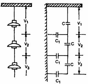
A string of suspension insulators consists of a number of porcelain discs connected in series through metallic links. The figure shows 3 strings of suspension insulators. The porcelain portion of each disc is in between two metal links. Shunt capacitance exists between porcelain discs as shown. The string efficiency is defined as the ratio of voltage across the whole string to the product of number of discs and the voltage across the disc nearest to the conductor. Thus,

where n is the number of discs in the string.
(i) using longer cross-arms
(ii) grading the insulators
(iii) using a guard ring.
Also Read: Single Phase Earth Return System


