Diode circuits, called limiters or clippers, are sometimes used to clip off portions of signal voltages above or below certain levels. Another type of diode circuit, called a clamper, is used to add or restore a dc level to an electrical signal.
Diode Limiters
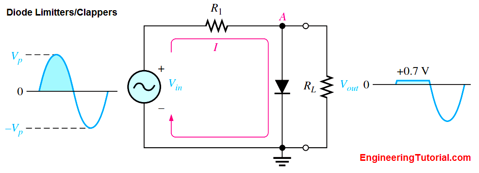
The Below Figure (a) shows a diode positive limiter (also called clipper) that limits or clips the positive part of the input voltage. As the input voltage goes positive, the diode becomes forward-biased and conducts current. Point A is limited to +0.7 V when the input voltage exceeds this value. When the input voltage goes back below 0.7 V, the diode is reverse-biased and appears as an open. The output voltage looks like the negative part of the input voltage, but with a magnitude determined by the voltage divider formed by R1 and the load resistor, RL, as follows:

If R1 is small compared to RL, then Vout α Vin.
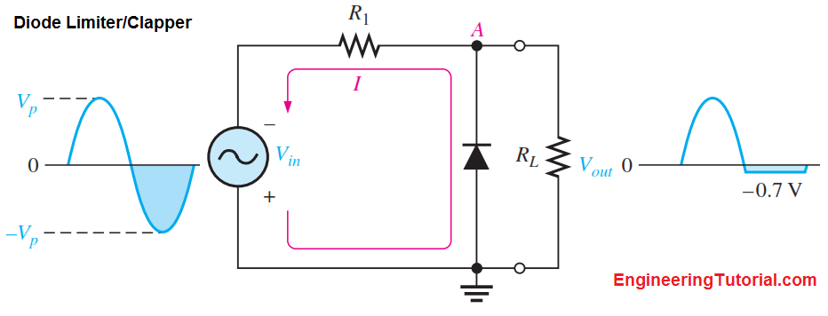
If the diode is turned around, as in Figure (b), the negative part of the input voltage is clipped off. When the diode is forward-biased during the negative part of the input voltage, point A is held at -0.7 V by the diode drop. When the input voltage goes above -0.7 V, the diode is no longer forward-biased; and a voltage appears across RL proportional to the input voltage.

Fig (a) : Limiting of the positive alternation. The diode is forward-biased during the positive alternation (above 0.7 V) and reverse-biased during the negative alternation.

Fig (b) : Limiting of the negative alternation. The diode is forward-biased during the negative alternation (below – 0.7 V) and reverse-biased during the positive alternation.


