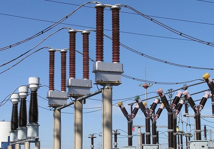
Current Transformers (CT) and Potential Transformers (PT) are used to measure the current and voltage in a circuit of the order of hundreds of amperes and volts respectively.
A CT has large number of turns on its secondary winding, but very few turns on its primary winding. The primary winding is connected in series with the load so that it carries full load current. A low voltage range ammeter (0-5A) is connected across the secondary winding terminals. Secondary of the CT is practically short circuited since the ammeter resistance is very low. It should be remembered that secondary of the CT should not be made open as it draws heavy current and damages the primary winding of the CT
A PT has large number of turns in the primary and fewer turns in the secondary and hence it steps down the voltage. The primary winding is connected across the supply voltage and low range voltmeter (0-110V) is connected across the secondary winding terminals
Some of the main difference between current transformers (CT) and potential transformers (PT) are given below:
- The secondary of the CT is almost short circuit, whereas the secondary of the PT is practically a open circuit
- The primary winding of the CT is connected in series with the load so that it carries the full line current, but there is only a small voltage across it. However the primary winding of the PT has the full supply voltage applied across it
- In CT the excitation current I0 and flux density vary over a wide range whereas in PT, they vary over a limited range only


