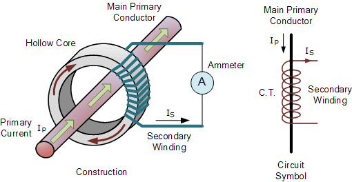
Current Transformer
In general, large currents (hundreds of amperes) cannot be directly input to powermeters for measuring power. Therefore, the current is passed through a CT (current transformer) prior to measurement. The following are some points regarding selection, operation, and maintenance of CTs.

Selecting a CT
- Check the voltage of the circuit.
Check the voltage of the circuit to be tested, then select a CT that supports that voltage. - Check the rated primary current.
Choose a CT with a rated primary current that is slightly larger than the maximum current that will be measured (ex.: 100 A, 200 A, 300 A, 500 A, 800 A). The rated secondary current is typically 5 A, but there are also 1-A transformers. Single ampere CTs are useful for long-distance wiring. - Check the rated load.
The load should be checked because it affects the wiring distance and other factors. See, “Operating a CT.” - Ampere-turn:If the primary current is a few amperes, winding the primary cable around the CT several times
 will cause the secondary current to be multiplied by just the number of times the cable is wound, allowing you to extract it. For example, if you wind a cable once around a 100 A/1 A CT, two turns of the cable will pass through the center of the CT resulting in a 50 A/1 A ratio.
 - Other:
To prevent accidents when the secondary circuit is open, it is safest to use a CT with a built-in voltage restraint.
Operating a CT
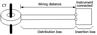
- The rated load is the sum of the distribution loss between the CT and instrument connected to the secondary side, and the insertion loss at the instrument connected to the secondary side. You should keep
 the value within this load rating, for example, an indication of 0.5 VA or 2.5 VA.CT rated load ≥ distribution loss + insertion loss at secondary sideTo calculate the distribution loss, see (2) and (3) below.
 - Check the wiring distance and material.
Loss grows proportionally larger with the wiring distance.
The total length of the wiring materials is the distance both ways.Approx. Resistance in Wiring Material
Nominal cross-sectional area: 1.25 mm²= Approx. 18 Ω/km
Nominal cross-sectional area: 2.0 mm² = Approx. 10 Ω/km - Examples (rough calculation)CT: rated primary current/rated secondary current = 100 A/1 A
CT’s rated load: 0.5 VA- When using wiring material with a nominal cross-sectional area of 1.25 mm²Wiring resistance R = 18 Ω/km × 0.015 km × 2 (both ways) = 0.54 Ω
Distribution loss ≈ I²R = (rated secondary current)² × wiring resistance = 1 × 1 × 0.54 = 0.54 VA
Condition: CT rated load > distribution loss + insertion loss of the instrument connected to the secondary side
This results in 0.5 < 0.54 + 0.2 = 0.74, which is false (the condition is not met). - When using wiring material with a nominal cross-sectional area of 2.0 mm2Wiring resistance R = 10 Ω/km × 0.015 km × 2 = 0.3 Ω
Distribution loss ≈ I²R = (rated secondary current)² × wiring resistance = 1 × 1 × 0.3 = 0.3 VA
Condition: CT rated load > distribution loss + insertion loss of the instrument connected to the secondary side
This results in 0.5 ≥ 0.3 + 0.2 = 0.5, which is true (the condition is met).
In the example above, wiring with a nominal cross-sectional area of 2.00 mm2 is required.
- When using wiring material with a nominal cross-sectional area of 1.25 mm²Wiring resistance R = 18 Ω/km × 0.015 km × 2 (both ways) = 0.54 Ω
Precautions Regarding Inspection and Maintenance
Never work on live wires. High voltage is generated when current is flowing through the CT and the secondary circuit is open. It is extremely dangerous to leave the device is a state in which dielectic breakdown seems likely to occur, as burns or fires can result. Therefore, always short the CT’s secondary circuit before turning on the electricity after performing maintenance. Recently, CTs with built-in voltage restraints for the secondary circuit have become available.
Also Read: Electrical Engineering Basics


