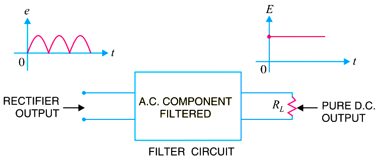
Generally, a rectifier is required to produce pure d.c. supply for using at various places in the electronic circuits. However, the output of a rectifier has pulsating character i.e. it contains a.c. and d.c. components. The a.c. component is undesirable and must be kept away from the load. To do so, a filter circuit is used which removes (or filters out) the a.c. component and allows only the d.c. component to reach the load.
A filter circuit is a device which removes the a.c. component of rectifier output but allows the d.c. component to reach the load.

Obviously, a filter circuit should be installed between the rectifier and the load as shown in Fig. A filter circuit is generally a combination of inductors (L) and capacitors (C). The filtering action of L and C depends upon the basic electrical principles. A capacitor passes a.c. readily but does not pass d.c. at all.
On the other hand, an inductor opposes a.c. but allows d.c. to pass through it. It then becomes clear that suitable network of L and C can effectively remove the a.c. component, allowing the d.c. component to reach the load.
Types of Filter Circuits
The most commonly used filter circuits are
- capacitor filter,
- choke input filter and
- capacitor input filter or π-filter.


