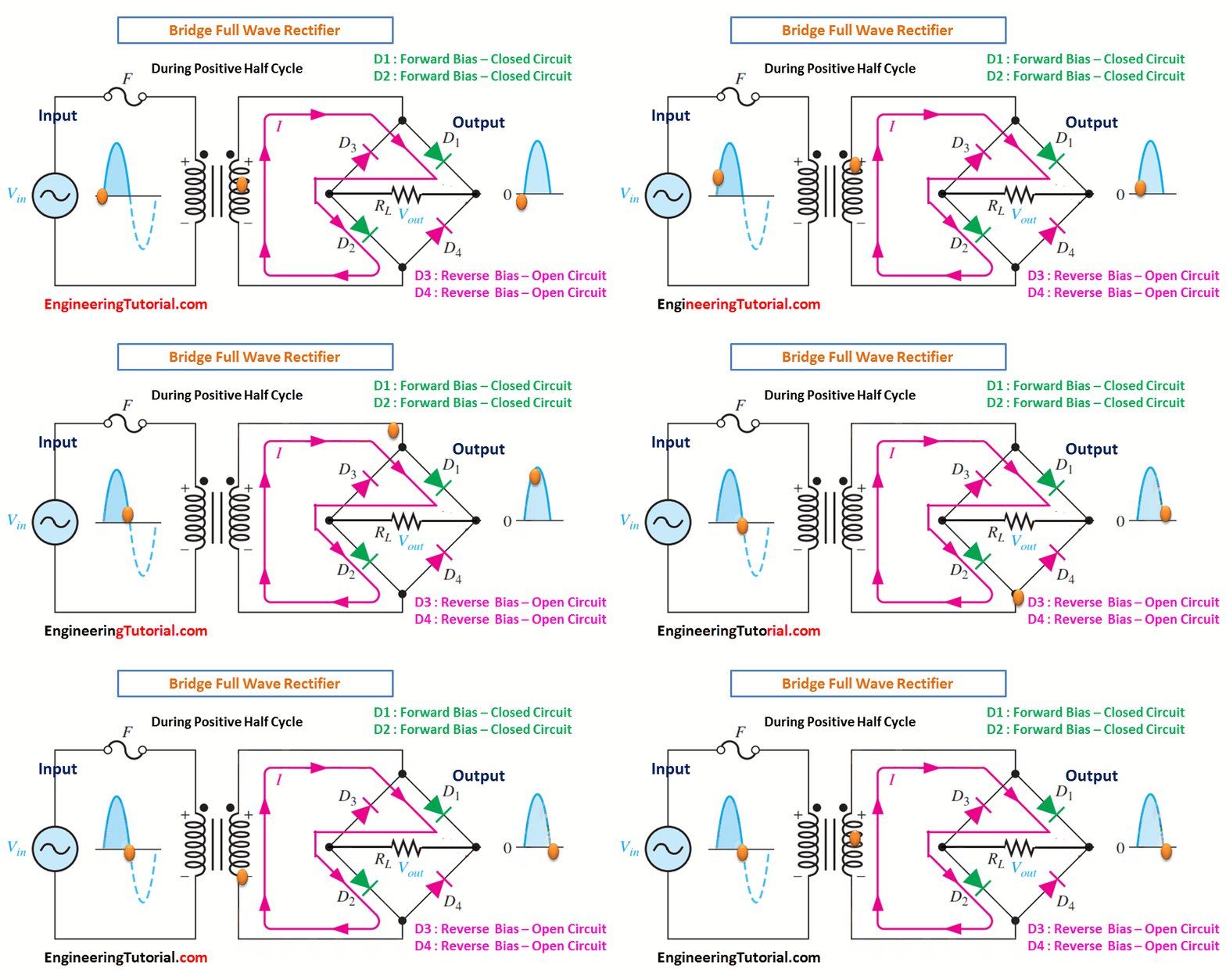
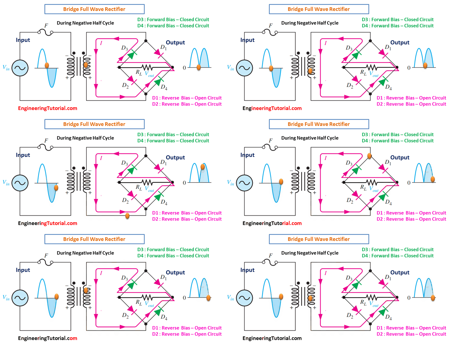
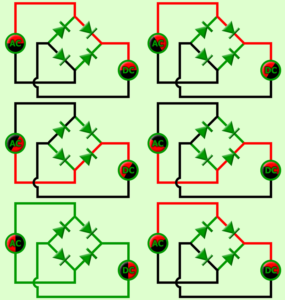
The bridge rectifier uses four diodes connected as shown in Figure. When the input cycle is positive as in part (a), diodes D1 and D2 are forward-biased and conduct current in the direction shown. A voltage is developed across RL that looks like the positive half of the input cycle. During this time, diodes D3 and D4 are reverse-biased.

(a) During the positive half-cycle of the input, D1 and D2 are forward-biased and conduct current. D3 and D4 are reverse-biased.

(b) During the negative half-cycle of the input, D3 and D4 are forward-biased and conduct current. D1 and D2 are reverse-biased.
When the input cycle is negative as in Figure (b), diodes D3 and D4 are forward-biased and conduct current in the same direction through RL as during the positive half-cycle During the negative half-cycle, D1 and D2 are reverse-biased. A full-wave rectified output voltage appears across RL as a result of this action.


Nice thanks