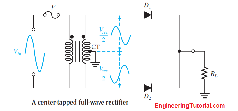
A center-tapped rectifier is a type of full-wave rectifier that uses two diodes connected to the secondary of a center-tapped transformer, as shown in Below Figure. The input voltage is coupled through the transformer to the center-tapped secondary. Half of the total secondary voltage appears between the center tap and each end of the secondary winding as shown.

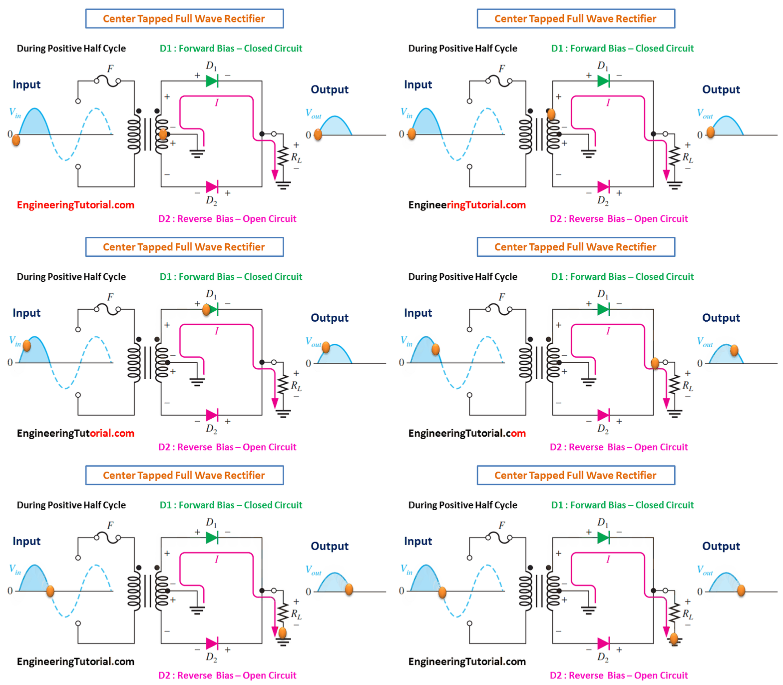
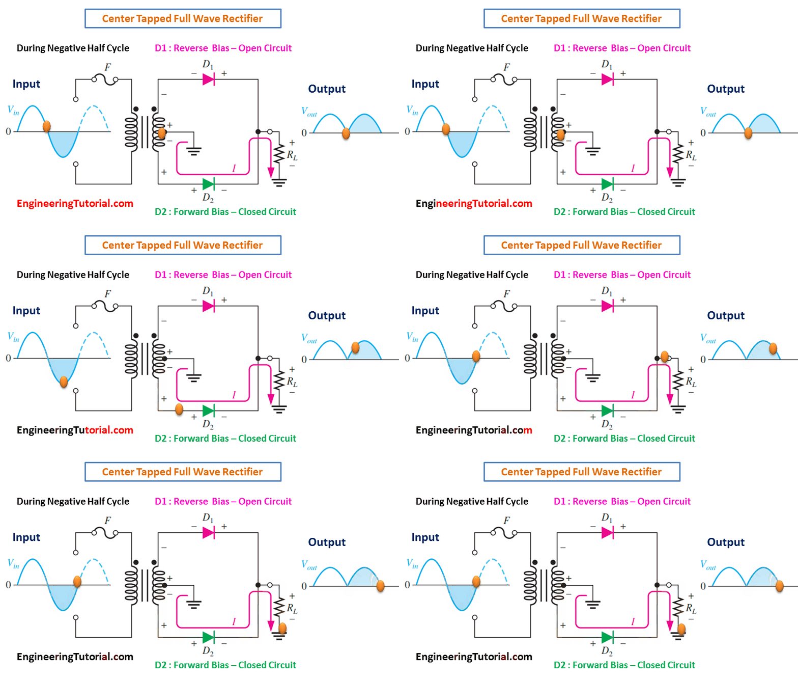
For a positive half-cycle of the input voltage, the polarities of the secondary voltages are as shown in Figure (a). This condition forward-biases diode D1 and reverse-biases diode D2. The current path is through D1 and the load resistor RL, as indicated. For a negative half-cycle of the input voltage, the voltage polarities on the secondary are as shown in Figure (b). This condition reverse-biases D1 and forward-biases D2. The current path is through D2 and RL, as indicated. Because the output current during both the positive and negative portions of the input cycle is in the same direction through the load, the output voltage developed across the load resistor is a full-wave rectified dc voltage, as shown.

(a) During positive half-cycles, D1 is forward-biased and D2 is reverse-biased.

(b) During negative half-cycles, D2 is forward-biased and D1 is reverse-biased.


