For transmission of more power for long distances to load centers Extra High Voltage (EHV) transmission is employed. Implementing Extra High Voltage has advantage of reduction in the copper losses and improves efficiency.
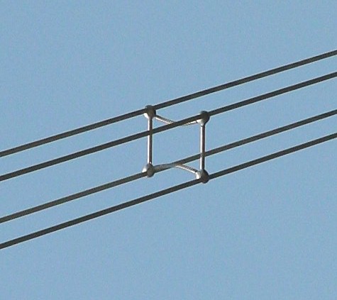
However transmission of voltage beyond 300kV will poses some problems such as Corona effect which causes significant power loss and interference with communication circuits if round single conductor per phase is used. In order to reduce corona effect hollow round conductors are used. Keeping economical constraints other option is instead of using hallow round conductor it is preferable to use more than one conductor per phase which is called Bundled Conductors. For transmission of power beyond 400kV bundled conductors are employed.

Advantages of Bundled Conductors:
Bundled conductors are primarily employed to reduce the corona loss and radio interference. However they have several advantages:
- Bundled conductors per phase reduces the voltage gradient in the vicinity of the line. Thus reduces the possibility of the corona discharge. (Corona effect will be observed when the air medium present between the phases charged up and start to ionize and acts as a conducting medium. This is avoided by employing bundled conductors)
- Improvement in the transmission efficiency as loss due to corona effect is countered.
- Bundled conductor lines will have higher capacitance to neutral in comparison with single lines. Thus they will have higher charging currents which helps in improving the power factor.
- Bundled conductor lines will have higher capacitance and lower inductance than ordinary lines they will have higher Surge Impedance Loading (Z=(L/C)1/2). Higher Surge Impedance Loading (SIL) will have higher maximum power transfer ability.
- With increase in self GMD or GMR inductance per phase will be reduced compared to single conductor line. This results in lesser reactance per phase compared to ordinary single line. Hence lesser loss due to reactance drop.


