Where Star (wye) Delta transformer is used in Power system
Star-Delta Transformer (Y-Δ )
Primary Y (High Voltage side) and Secondary ( Low Voltage side) Δ is generally used at the generating side for stepping up the voltage levels. Power is generated at 11kV to 33kV having current ratings in thousands of kilo amps. This generation voltage has to be stepped up to higher voltage for transmission as stepping up the voltage results in the reduction of losses while transmission
Generation side of the transformer (LV side) voltage applied is low and current flowing through the windings of the transformer is high. At secondary side (LV side), delta connection (Δ) is employed because in delta connection Iphase=ILine/√ 3 and Vphase=VLine
Current carrying capacity of windings depends on the thickness of the conductor. Large current flowing through the conductor means more copper utilised for the windings. Therefore in order to reduce the flow of huge currents by above equation delta winding is employed in the LV side of the transformer
On the other hand star type (Y) of connection is employed on the HV side of the transformer. In star connection Vphase=VLine/√ 3 and Iphase=ILine
Voltage withstand ability of conductor depends on the insulation strength of the conductor. Hence to reduce the phase voltage Star (Y) connection is employed in the high voltage (HV side) of the transformer.
Why Transformer makes Hum noise ?
Transformer makes “hum” noise because of Magnetostriction effect. Magnetostriction effect is the property of ferromagnetic magnetic such that change in the dimension of material when the varying magnetic field is applied.
In electrical transformer alternating voltage is applied to the core. This results in the varying magnetic filed direction in the core. Grain directions will be varied in every half cycle. Due to this varying magnetic field, dimensions of the material will be changed causing the vibrations.
Some of the methods employed to reduce the noise are:
- Preventing vibration of core-plate, which use the lower flux density
- Tightly bolting and clamping the laminations and structural parts of the transformer
- Sound insulating the transformer from the tank by cushions, padding and oil barriers
- Preventing transformer tank wall vibration by suitable design of tank and stiffeners
- Sound insulating the tank from the ground or surrounding air
Why Silica gel is used in transformer
When load on transformer increases current flowing the transformer windings increases. Heat generated by the rise in the current will be dissipated in to the transformer oil. Heated transformer oil becomes less denser compared to the normal transformer oil and moves up in to the conservator. This heat will be dissipated in to the atmosphere from hot transformer oil.
When load on transformer increases, transformer breather breathes air in. Air contains moisture when come in contact with the oil will affect the purity of the transformer oil. Moisture and impurity level in the transformer oil increases results in the damage of insulation property of the transformer oil.
To avoid entry of moisture air in to the transformer silica gel crystals are used. Silica gel will absorb the moisture in the air and allows dry air in to the transformer. Silica gel will be blue when they are installed or dry. When the crystals absorb the moisture they turn to pink color.
Thus silica gel protects the insulation strength of the transformer oil by absorbing the moist air entering in to the transformer
How Transformer Impedance is designed
Certain considerations were determined while designing the impedance value of the power transformer. Impedance for the transformer is due to the inductance and resistance present in the transformer.
During short circuit in the power systems short circuit current in the power system is limited by the presence of impedance drop due to transformers, transmission lines and cables. These impedance drops in the power system reduces the short circuit level. This the advantage of having high impedance values for the transformer.
However large transformer impedance cause large drop in the power system during the normal operation. This will cause a significant impact on the starting of the large motors (when large motors are started during low voltage condition other loads connected to the bus will trip due to huge drop in voltage at the bus) and voltage regulation of the power system
Hence transformer impedance is designed for a optimum value considering the above conditions.
Why Transformer rating is in KVA not kW
Rating of Electrical Transformer is in VA (Volt Amperes ) because:
Maximum current carrying capacity of the transformer is determined by the thickness of the conductor and Maximum voltage supplied to the winding depends on the insulation strength of the conductor
Manufacturers of Transformers and alternators does not know at what power factor the consumer uses the machine and the nature of the load (capacitive, resistive and inductive) connected to the machine. Hence they rate the transformer depends on the maximum current carry and the voltage to be applied. This rating of the transformer corresponds to apparent power of the machine (VA). Also iron losses in transformer depends on the the voltage applied and copper losses depends on the current flowing through the winding. These losses are independent of the power factor at which the transformer operates.
On the other hand induction motors are rated with real power (Watts) as the machine operating at defined power factor at full load is pre determined.
Eg: Consider a transformer can carry maximum current of 50A and max voltage applied is 200V. Then
Power rating of the at full load (Unity power factor) = 50×200 = 10kW
Power rating of the at full load (0.5 power factor) = 50x200x0.5 = 5kW (This means load having 0.5 power factor can connect maximum of 5kW to the transformer. 5kW is the full load of the transformer)
Low Voltage winding near core of the Transformer
For explaining the operation of the transformer Low voltage winding (LV winding) and High voltage winding (HV winding) are wound on different limbs of the transformer for easy explanation. However in practical each limbs of the core will have both LV winding and HV winding wound together.
In Transformer design LV winding will be wound close to the core of the transformer because the insulation provided between the LV winding and core of the transformer is quite less compared to the insulation provided between the HV winding and the core of the transformer which results in less cost for insulation and reduction in the size of the transformer for same MVA rating. Hence due to this reason LV winding is placed near to the core of the transformer.
On the core of the transformer insulation is placed and LV winding is wound. Once again insulation is placed between the LV winding and HV winding.
All Day Efficiency of Transformer
Transformer Efficiency:
Core losses in electrical transformer remains same through out the operation of the transformer irrespective of the load on the transformer. However copper losses which occur due to the resistance of the winding (I2R) vary with the load on the transformer.
In some types of transformers (Distribution Transformers) performance or efficiency cannot be determined by the ordinary efficiency calculations. For instance consider the distribution transformers supplying power to the house and industrial loads, these transformers will not have constant load and load varies throughout the day. During night times most of the load demand comes down results in the less load on the transformer. The performance of such transformers are determined through it all day efficiency which means efficiency is computed on the basis of the energy consumed during the whole day (24 hours ).
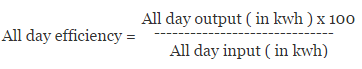
All day input = All day output + Iron losses + copper losses (calculated for 24 hours)
Distribution transformers will not supply the rated load for the full day. Therefore all day efficiency of distribution transformers will be less than ordinary efficiency or commercial efficiency. Most of the time load on distribution transformer will be between (50% to 75%). Therefore distribution transformers are designed for maximum efficiency at half load. On the other hand power transformers are designed to have maximum efficiency at near the full load.
Induction Motor Rotating Transformer Relation
Relation between Transformer and Induction Motor:
Induction motor and Electrical Transformer operates on the same Faraday’s law of electro-magnetic induction principle.
In Electrical Transformer when voltage is applied to the primary winding, it draws magnetising current and load current. Magnetizing current is required to magnetize the core of the lamination. This magnetizing current produces flux which travels to the secondary winding of the transformer and completes the closed loop back to the primary winding through the magnetic core of the transformer.
In Induction motor there is no electrical connection to the rotor. When a 3-phase voltage applied to the stator winding it produces a rotating magnetic field which rotates at synchronous speed. When the flux cuts the stationary rotor conductors an emf is induced similar to the emf induced in the secondary side of the transformer. As the rotor winding of the induction motor is short circuited (Closed) current flows through the rotor which sets up the torque of the rotor.
The main difference between the electrical transformer and induction motor is in electrical transformer magnetic path is a closed one through the core of the transformer. On the other hand, in induction motor air gap present between the stator and rotor windings. For obtaining electro-mechanical conversion air gap is required. Thus Induction motors are considered as rotating transformers
Why Low Voltage (LV) winding is placed near to the transformer core?
For a given conducting material insulation required depends on the voltage. Hence if High Voltage (HV) winding is placed near to the transformer core, more insulation is required to insulate between the transformer core and the High Voltage (HV) winding. This results in increase in the cost of the insulation material and also size of the transformer increases significantly. Thus Low Voltage (LV) winding is placed near the core which requires less insulation between the core and LV winding.
What are the different insulation materials used in power transformers?
In power transformers the primary insulation medium and cooling medium is transformer oil. It serves the purpose of both insulation and cooling. Apart from transformer oil different insulation materials employed are oil impregnated paper, press board, wood, mica, and asbestos.
What is Transformer Breathing?
When transformer under full load, power transformer oil present in the transformer heats up and gets expand. During this process gas at the top of the oil gets expel out in to the conservator present at the top of the power transformer along with hot oil and cool oil from conservator comes down. This process is called breathing out of the transformer.
When the load on the power transformer is removed or during no load condition, transformer oil cools and air is drawn in to the transformer. This is called breathing in of the transformer. The incoming air may consists of moisture which should be removed else results in the deterioration of the dielectric strength of the transformer oil. Hence the air entering the power transformer is made to pass through the breather where moisture is removed from air through silica gel.
Transformer Testing methods
Transformer Tests:
Tests on the transformers are carried for verifying the capabilities of transformer to withstand Thermal stresses, Dielectric stresses, short circuit electro-dynamic stresses and environmental stresses.
Routine tests:
These are carried out on every transformers before dispatch to ensure that it is in accordance with the specifications.Some of the tests come under routine test include:
- Measurement of the winding resistance
- Verifying the polarity of the windings
- Measurement of load losses and the impedance voltages
- Measurement of no load losses and no load no load current.
- Electrical tests at the power frequency
Type Tests:
Type tests are performed on the first transformer of one type and are intended to check the design characteristics. It is presumed that every transformer would also comply with the type test, since its design is identical.
- Temperature rise test
- Tests of ability to withstand full wave impulse
- Tests for switching impulse withstand
- Noise level test
Special Test:
Special tests are conducted in the presence of the purchaser or his representatives as specified in the tender
- Partial discharge test
- Checking the level of Radio interference voltage
- Vibration test
- Test on ability to withstand Short -circuit current
- Measurement of Noise level