How to test TRIAC with Digital Multimeter OR using Ohmmeter?
In this shot post we will discuss about how to test the Triac.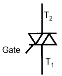 Introduction about Triac:
- TRIAC = TRIode for Alternating Current.
- The TRIAC is 5 layer, 3 terminal Power semiconductor device.
- It has a pair of phase controlled SCRs connected in inverse parallel manner on the same chip.
- It is a bidirectional device, means it can conduct current in both the directions.
Step by step Procedure to test the triac:
- Keep the digital multimeter into Ohmmeter mode.
- Using a junction diode determine which ohmmeter lead is positive and which is negative. The ohmmeter will indicate continuity only when the positive lead is connected to the anode and the negative lead is connected to the cathode.
- Connect the positive lead of Ohmmeter to MT2 and the negative lead to MT1. The ohmmeter should indicate no continuity through the triac.
- Using a jumper lead connect the Gate of the Triac to MT2. The multimeter should indicate a forward diode junction.
- Reconnect the Triac so that MT1 is connected to the positive lead of ohmmeter and MT2 is connected to the negative lead. The multimeter should indicate no continuity through a Triac.
- Using a jumper lead, again connect the gate to MT2. The ohmmeter should indicate a forward diode junction.
Related Articles :
Engineering Tutorial Keywords:
- how to test a triac
- test triac
- testing triac with multimeter
- testing a triac
- triac test