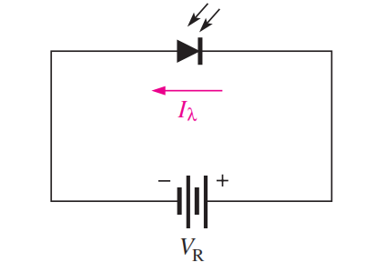
The photodiode is a device that operates in reverse bias, as shown in Figure.
where Ia is the reverse light current. The photodiode has a small transparent window that allows light to strike the pn junction.

In reverse-biased, a rectifier diode has a very small reverse leakage current. The same is true for a photodiode. The reverse-biased current is produced by thermally generated electron-hole pairs in the depletion region, which are swept across the pn junction by the electric field created by the reverse voltage. In a rectifier diode, the reverse leakage current increases with temperature due to an increase in the number of electron-hole pairs.
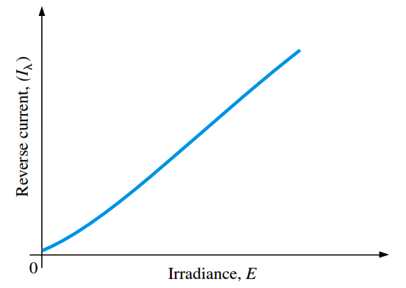
A photodiode differs from a rectifier diode in that when its pn junction is exposed to light, the reverse current increases with the light intensity. When there is no incident light, the reverse current, I, is almost negligible and is called the dark current. An increase in the amount of light intensity, expressed as irradiance (mW/cm2), produces an increase in the reverse current, as shown by the graph in Figure (a).
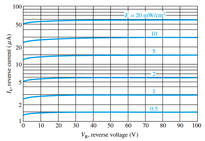
From the graph in Figure (b), you can see that the reverse current for this particular device is approximately 1.4 mA at a reverse-bias voltage of 10 V with an irradiance of 0.5 mW/cm2.
Therefore, the resistance of the device is

These calculations show that the photodiode can be used as a variable-resistance device controlled by light intensity.
Typical photodiode characteristics

Fig (a) : General graph of reverse current versus irradiance

Fig (b) : Example of a graph of reverse current versus reverse voltage for several values of irradiance
