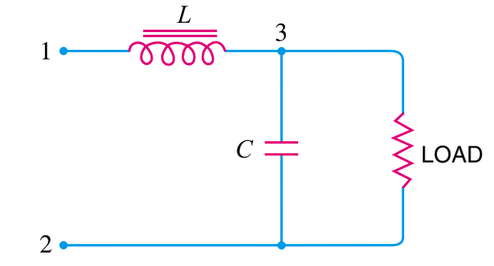
The below Fig. shows a typical choke input filter circuit. It consists of a Choke L connected in series with the rectifier output and a filter capacitor C across the load. Only a single filter section is shown, but several identical sections are often used to reduce the pulsations as effectively as possible.

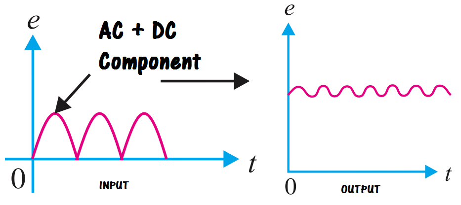
The pulsating output of the rectifier is applied across terminals 1 and 2 of the filter circuit. As discussed before, the pulsating output of rectifier contains a.c. and d.c. components. The choke offers high opposition to the passage of a.c. component but negligible opposition to the d.c. component. The result is that most of the a.c. component appears across the choke while whole of d.c. component passes through the choke on its way to load. This results in the reduced pulsations at terminal 3.


